Advances in Servo Track Writing (STW) Technologies: A Review

Copyright © The Korean Society for Precision Engineering
This is an Open-Access article distributed under the terms of the Creative Commons Attribution Non-Commercial License (http://creativecommons.org/licenses/by-nc/3.0) which permits unrestricted non-commercial use, distribution, and reproduction in any medium, provided the original work is properly cited.
Abstract
Since IBM introduced the first hard disk drive (HDD) with 5 MB capacity in 1956, tremendous advances have been achieved in HDD technology and business. The areal density has increased 650 million times in the last 60 years. To implement the digital servo systems for high capacity HDD, elaborate servo patterns should be written on the disk surface during manufacturing processes. This process is called servo track writing (STW). When the servo track pitch reaches 50 nano-meter, the position error resolution should be less than 5 nano-meter for the drive servo and STW operations. The STW technology is in the realm of nano-mechatronics and should address precision motion control and manufacturing issues. Initially, all STW process were conducted inside the clean-room using special STW equipment. With ever-increasing track density, as well as the STW time and manufacturing costs, the industry has developed the STW technology that could move the STW operation to the outside of the clean-room and eliminate special equipment. Many innovative STW technologies have been invented and successfully implemented such as conventional STW, multi-disk writers, printed magnetic printing STW, spiral STW and spiral-seeded STW. With the successful implementation of these state-of-the-art technologies, HDD production has become more efficient and flexible.
Keywords:
Servo track writing technology, Hard disk drive, Servo system development, Ultra-precision motion control, Electronics manufacturing, Nano-mechatronics키워드:
서보 트랙 라이팅 기술, 하드디스크 드라이브, 서보 시스템 개발, 초정밀 위치제어, 전자기기 제조, 나노 메카트로닉스1. Introduction
With proliferation of general purpose computers in early 1950s, the need for reliable non-volatile secondary storage devices had been grown steadily. In 1956, IBM introduced the first “hard disk drive (HDD)” based on spinning magnetic disks and non-contact flying read/write heads that was the size of a large refrigerator and stored amazing 5 megabytes (MB) at the time. With everincreasing demand for large capacity HDD, the HDD industry created lots of new technologies that have enabled the capacity increase in terms of areal density from 2000 bits per square inch in 1956 to 1.3 terabits per square inch in 2015 - that is 650 million times increase.1
Some notable technical advances are invention of magnetoresistive (MR) sensors as magnetic readers; application of perpendicular magnetic recording; implementation of dynamic flyheight control of read/write heads to maintain less than two nanometer gap between magnetic heads and the media; use of a fluid dynamic bearing (FDB) for a disk pack spindle motor; application of a dual-stage micro-actuator to significantly increase the servo bandwidth and consequently to enhance the drive servo performance. All these technologies have helped to increase the data track density in the disk radial direction as well as the linear density in the disk rotational direction.
The digital servo system has been employed to achieve high speed read and write of user data on the disk.2-5 Since a high performance digital positioning system requires accurate position information with reasonable sampling rate, sophisticated servo patterns have been pre-written on all disk surface for fast retrieval of the position information of a magnetic head. This process is called the servo track writing (STW) process. After a HDD is assembled inside the clean-room, the drive has to go through the STW process to write down embedded servo patterns on all magnetic surfaces. These embedded servo sectors are invisible to users and should never be overwritten.
As the data track density increases, so does STW time. Latest high capacity HDDs pack up to 20,000 tracks per millimeter. If these drives have to be servo-written inside the clean-room, it would take few hours of the STW time each. The investment for the STW process and clean-room space could be prohibitively high. Researchers and engineers have worked hard to bring up new STW technologies that would maximize the productivity and minimize the capital investment.6-10
In this paper, a brief history of computer hard disk drives has been described as computing focus has been shifted from main frame computers, to personal computers, and to cloud computing. Technologies related to HDD servo systems have been explained: open-loop servo, closed-loop servo, dedicated servo systems and embedded servo patterns. Evolution of servo track writing technologies covering conventional push-pin STW, media disk writer (MDW), magnetic printing STW, and self servo write has been described. A self servo track writing scheme based on spiral reference patterns is also presented. Finally, spiral-seeded self STW methods are explained as the “ultimate” servo track writing.
2. Brief History of Computer Hard Disk Drives
2.1 Main-Frame Computer Era
The IBM 305 RAMAC (Random Access Method of Accounting and Control) was the first commercial computer that used a moving-head hard disk drive (also known as magnetic disk storage) for secondary storage. Fig. 1 shows a picture of IBM 350 disk storage unit. The 350 stored 5 million 6-bit characters (3.75 MB). It had fifty 24 inch (610 mm) diameter disks with 100 recording surfaces. Each surface had 100 data tracks. The disk pack was spinning at 1200 RPM. The size of this storage sub-unit was about that of a large refrigerator and weighed over 2000 pounds (910 kg).11-13

The first computer hard disk drive introduced in 1956: IBM 350 disk storage unit for IBM 305 RAMAC system
Since 1956, the magnetic disk drive has been the main secondary storage device replacing or augmenting punch cards, magnetic tapes, magnetic drums, diskette drives and so on. In 1960-70s, main-frame computers had been the backbone of the computer industry and IBM dominated the market until mid-1980 when potent personal computers emerged. Naturally, many breakthroughs in the HDD technology had been mostly achieved by IBM scientists. Fig. 2 shows the last generation HDD for mainframe computers that costed up to $275,000 per unit. It has nine 11 inch (279.4 mm) disks.

The last HDD for main-frame computers: IBM 3390 introduced in 1989 - the maximum capacity was up to 22.7 GB
2.2 Personal Computer and Cloud Storage Era
Demand for personal computers (PC) had been rapidly increased after Apple and IBM introduced their own PCs in early 1980s with reasonable performance and cost. Affordable high capacity storage units for PC had been also in high demand. The ST506 HDD shown Fig. 3 was the first 5.25 inch hard disk drive for personal computers, introduced in 1980 by Shugart Technology (now Seagate Technology). It stored up to 5 MB after formatting and costed US $1,500 (equivalent to $4,561 in 2018). By the late '80s, hard disk drives were standard on all but the cheapest PC and floppy disks were used almost solely as transport media. Thomson and Best of IBM discussed feasibility and limitation of magnetic storage technology.14

Seagate ST506: the first 5.25 inch HDD for personal computers with a cover removed. Note a stepper motor actuator in the upper right corner
The larger form factors (5.25 inch and bigger) had been died off, while several smaller form factors were offered but achieved limited success, e.g. Toshiba-Samsung 1.8 inch drives, HP 1.3 inch Kittyhawk, IBM 1inch Microdrive, etc. The industry production is now consolidated around the 3.5 inch and 2.5 inch form factors. The number of HDD manufacturers peaked with about 75 active manufacturers in 1985. As of 2019, the HDD industry is highly consolidated into only three remaining manufacturers: Seagate, Western Digital and Toshiba. Unit production peaked in 2010 at about 650 million units and has been in a slow decline since then. Shipments in 2018 estimated at about 370 million units.1
While the volume of 2.5 inch HDD will continue to decline due to increased shipment of solid-state dives (SDD) for laptop PC, it is expected that the demand of high capacity 3.5 inch drives for data centers and consumer electronics applications such as digital video recorders will increase in coming years. This is due to considerable growth in world-wide data creation. It is estimated that the yearly production volume of HDD will be steady around 300 million units until 2025.1
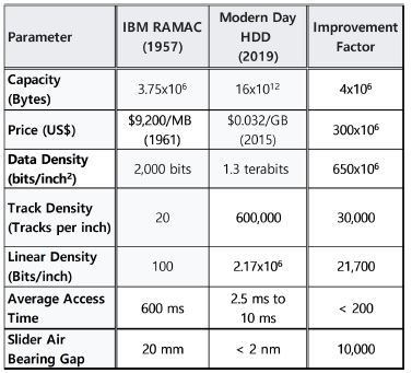
Table 1 shows the improvement of HDD characteristics from the first HDD to today. With rapid increase in capacity and fast drop in price, HDD has become a dominant mass stroage device for many applications. Note huge increase in both linear and track density. This has been achievable due to substantial advances in both recording and servo technologies.

Improvement of HDD characteristics and performance
3. Development of HDD Servo Systems
3.1 Open-Loop Servo Control
With low track density, magnetic tracks can be written and read in open-loop fashion by use of a stepper motor actuator. This implies that the actual head position is estimated from encoder readouts located in a stepper motor shaft. While a magnetic head-stack is lineraly actuated by a stepper motor as shown in Figs. 3 and 4 displays a rotaty actuation such that the head-stack is connected to a stepper motor through a linkage. These HDDs were still an expensive option for personal computers in early 1980s.

Seagate ST225: a 5.25 inch, 20 GB HDD with open-loop servo scheme. A stepper motor is shown in the upper right corner
3.2 Closed-Loop Servo System
With ever-increasing track density, temperature variations, and external vibrations, the open-loop servo control was no longer feasible for high capacity HDDs. Even though IBM employed a closed-loop servo control for its expensive disk drives for mainframe computers, a low-end HDD for PC was slow to adopt the closed-loop servo system. A linear voice coil motor (VCM) was used as an actuator to move a head-stack (or E-Block) for first few generations of the HDD servo system in late 1980s. Fig. 5(a) shows an example of linear VCM application for a 5.25 inch HDD.

(a) Seagate ST4096: a 5.25 inch HDD with a linear voice coil motor (VCM) and (b) A modern-day HDD with a rotary VCM
Since a linear VCM is expensive and more susceptible to external shock and vibrations, all modern HDD are built with a rotary VCM actuator that is simple, economical, and provides compact packaging. However, with rotary actuators, the servo system should compensate for head skew, since the head gap does not remain parallel to a disk radius as a function of angle of rotation. Also with unwanted dynamics of rotary actuators, the control system bandwidth is rather limited.2
Fig. 5(b) demonstrates typical mechanical components inside a HDD. In order to achieve fast increasing capacity and track density, some mechanical components have been improved or invented. These are fluid dynamic bearings (FDB) for a spindle motor, dynamic fly height control to minimize and regulate the gap between the magnetic head and disk, dual-stage micro-actuators for significant increase of servo bandwidth, and helium-filled drives to minimize disturbances due to air turbulence inside HDD.
Since 1987 when the digital servo was introduced for mass production HDD, various control algorithms have been applied to HDD servo system and the substantial servo performance enhancement has been achieved. A 3.5 inch HDD capacity, which was 250 MB in 1988, has increased to 16 TB in 2019 - 64,000 times increase! For a 500,000 TPI (Tracks per inch) HDD, the track pitch is 2 × 10⁻⁶ inch or 50 nano-meter. This is equivalent to 20,000 tracks per millimeter. In order to achieve adequate servo performance in track-following or seeking mode, it is recommended that the position error resolution should be at least 1/10 of the track pitch. Hence for this drive, the position resolution should be at least 5 nano-meter.
Fast data track access, nanometer-scale positioning, robustness against environmental changes and plant dynamics variations, and rejection of various disturbances have been required for HDD servo system to achieve the target capacity.3 Franklin et al. skillfully explained on general principle and methods of designing a disk drive servo system.2,4 Abramovitch and Franklin wrote an excellent paper on the brief history of disk drive control.5
With very high volume production of HDD, it is usually expensive to modify or improve mechanical components. Hence whenever there is a chance, intelligent modern control algorithms have been applied to resolve certain servo-mechanical problems. These are adaptive feedforward compensation (AFC) algorithms to resolve issues related to repeatable runouts (RRO), adaptive notch filters to suppress unwanted mechanical resonances with varying frequency, the disturbance observer algorithm coupled with accelerometer measurements to compensator external vibrations, the loop-shaping technique to minimize disturbances in a certain range of frequencies, and so on.16-18
4. Evolution of Servo Track Writing (STW)
4.1 Dedicated Servo System
Fig. 6 illustrates a HDD servo system based on a dedicated servo disk (or a surface). The track position information has been pre-written on a dedicated “servo” disk - either the top or bottom disk of a disk pack. All magnetic heads on a head stack (or E-Block) are moving together based on position readouts of a “servo head.” With the dedicated servo-disk scheme, while the position information could be continuously fed into the servo system, the overall capacity of the drive would be lower due to a dedicated servo surface.13 Moreover, with rapid increase in track density, it was getting more difficult to repeat precise writing and reading operations due to sensitivity to disk pack misalignment and temperature variations.

Dedicated servo disk for HDD closed-loop control
4.2 Embedded Servo Pattern System
In order to mitigate shortcomings of the dedicated servo system, the embedded servo pattern technology had been invented and integrated into all modern HDD. Fig. 7 shows a schematic of the embedded servo system. Servo wedges (or sectors) are spaced in the predetermined interval that defines the sampling frequency of the disk drive servo system. The disk drive controller splits the processing time between user data read/write, and servo data processing and control. Servo wedge area is strictly protected by the control system not to overwrite the prewritten servo information.

Embedded servo pattern technology
Each servo wedge is composed of elaborate signal patterns that provide precise position information to a digital servo system. Fig. 8 illustrates signal patterns inside a servo wedge: the servo preamble synchronizes the digital system for servo information processing; Servo address mark (SAM) checks and finds the servo sector number and head number; the gray code is a digital information of track number (or cylinder address); the A-B-C-D bursts provide analog information regarding the actual head position within a track.

Detailed signal information inside the embedded servo sector
Writing these elaborate servo patterns on every disk surface is called “servo track writing (STW)”. Due to half-track spacing of the A-B-C-D burst signals in the radial direction, the STW step is half of the servo track pitch. In other words, in order to complete the servo pattern of each servo track (or a cylinder), two STW steps are required. Once HDD is fully assembled, and finished with STW and calibration processes, the drive is ready for customer use. The servo demodulation block inside application-specific integrated circuit (ASIC) chip processes the servo signal from each servo sector and generates the position error signal (PES) for the digital servo system so that track-following or seeking commands could be executed and data read/write operations be accomplished.
As for any digital control system, the most critical parameter is the sampling frequency that is the number of servo wedges per revolution for the disk drive servo system. While higher sampling frequency is preferred for high performance digital control system, increase of servo wedges reduces the available user data capacity. As a general rule of thumb for HDD servo system design, the servo sector (or overhead) should occupy less than 5% of the overall disk capacity. The enterprise-class HDD with high RPM such as 10,000 or 15,000 RPM employs high sampling rate to support high speed read/write performance. The mobile HDD for laptop computers also requires higher sampling frequency in order to quickly detect and compensate external shocks or vibrations. Meanwhile the 3.5 inch HDD for desktop computers can live with moderate sampling rate.
4.3 Conventional Push-Pin STW (CSTW)
All mechanical components shown in Fig. 5(b) are assembled inside the clean-room. Since there is no servo information on blank disks, an external device with a precision motion control system is attached to the drive through a push pin that pushes and moves the E-Block (or head-suspension assembly) while writing servo patterns on all disk surfaces. This external position control device is called a “conventional push-pin servo track writer (CSTW)”.
In order to control the push-pin positioner of the CSTW and write precise servo patterns on a magnetic disk, a sophisticated electronic hardware was integrated into the system. The early generation of CSTW employed an expensive laser interferometer for position sensing of the head stack.15 Later, a cost-effective positioner based on an optical encoder, as shown in Fig. 9, replaced a combination of a laser interferometer and rotary VCM. Various techniques to improve CSTW were discussed by Uematsu and Fukushi.6

A conventional push-pin servo track writer with a rotary actuator and an optical encoder
As described in Section 4.2, two STW steps are needed to complete the servo pattern of one servo track. For a 3.5 inch drive with 500,000 servo tracks, it is estimated that STW time is about 3.7 hours per drive (8.3 milliseconds per revolution for a 7200 RPM spindle; 13.3 msec STW time with seek-settle overhead × 1,000,000 STW steps = 13,300 sec = 3.7 hours). This implies that, in order to build 1,000,000 HDD per month, more than 5,000 CSTW inside the clean-room would be required. Hence full servo pattern writing with CSTW is rarely done for modern HDD production.
4.4 Offline Media Servo Track Writer
In order to increase the productivity of servo track writing operations inside the clean-room, an offline media STW or multi-disk writer (MDW) was developed. In this case, instead of writing servo patterns for each assembled HDD, 10 to 20 magnetic disks are stacked together on a spinning hub and servo patterns are written all at once in high RPM. With a high performance airbearing spindle and a precision head-stack (or E-Block) actuator, higher quality servo pattern writing is feasible with MDW. Then pre-written disks are assembled into a drive. Fig. 10 shows an example of a MDW machine inside the clean-room.

A disk pack loaded into a media servo track writer or multi-disk writer (MDW)
Yamada et al. explained the MDW technology in detail as well as other STW technologies.7 Whenever magnetic disks are assembled into a drive spindle hub, there is always some eccentricity. The drive servo system should adequately compensate this eccentricity for reliable reading of servo signals, reasonable track-following and seeking performance.8,16-18
5. Advanced Servo Track Writing Technology
5.1 Need for Advanced Servo Track Writing Technology
Due to rapid expansion of personal computer business and digital data explosion, the HDD production volume has been dramatically increased from 28 M units in 1990 to 650 M units in 2010. As the demand for high capacity HDD keeps going up, the track density requirement has been also significantly increased from 3000 TPI (track per inch) in 1990 to 400,000 TPI in 2010. Since STW time is directly proportional to the number of servo tracks or the track density (or TPI), the industry should cope not only with technical challenges related to high TPI but also with rapidly increasing STW time, tremendous factory clean-room space and STW equipment investment.
Since both CSTW and MDW methods require expensive hardware equipment and clean-room space, STW engineers have to focus on minimizing STW time inside the clean-room or completely moving STW operations to the outside of the clean-room.
5.2 Magnetic Printing Servo Track Writing (MPSTW)
One of the ideas to replace CSTW or MDW is to magnetically print servo patterns out of the master disk. Fig. 11 depicts the magnetic printing servo track writing (MPSTW) process. The master disk is lithographically patterned on top of the soft magnetic under-layer. Then the final servo pattern is transferred to a target magnetic disk by applying external magnetic field to reverse the polarity of magnetization corresponding to the groove on the master disk.7 Then, magnetically printed disks are assembled into a HDD.

Magnetic printing servo track writing (MPSTW)
This MPSTW process can be done during magnetic media production in a media factory. Although MPSTW provides many benefits, it is expensive to fabricate a master disk, more challenging to generate very high TPI servo patterns, and prone to propagate defective patterns or contamination in the master disk to target disks. Hence only limited number of HDD in early 2000s had been produced with this MPSTW technology.
5.3 Self-Servo Track Writing (SSW)
In 1997, IBM engineers invented self-servo track writing (SSW) that did not require any special equipment inside the clean-room.9 They developed sophisticated algorithms to start special startup patterns on the blank disk, to control pre-determined track pitch interval in the radial direction and constant servo sector timing interval in the circumferential direction. Moreover, since all magnetic heads were activated together and all disk surfaces were simultaneously written (so-called “Bank” writing scheme), significant reduction in STW time had been achieved. Although SSW savs the cost related to extra STW equipment and the clean-room space, it does require special electronic hardware to control the “radial” and “timing” propagation as well as spindle speed and additional drive functions. Kang et al. proposed a novel servo algorithm to compensate the radial error propagation due to written-in repeatable runout (RRO) in the seed track and external disturbances.19 Millions of HDD have been manufactured by use of SSW for IBM/HGST/Western Digital Company.
6. Servo Track Writing based on Spiral Reference Pattern
6.1 Spiral Servo Track Writing (SSTW)
In order to reduce the manufacturing cost related to STW operations, Swearingen and Shepherd invented self-servo writing scheme based on seeded (or reference) spiral pattern in 1997.10 Fig. 12 shows an idea of generating spiral reference patterns. Then by utilizing these “seeded” spiral reference patterns, the drive electronics would deduce both radial position and sector timing information, and subsequently write the final product servo pattern sequentially - that is, “self-propagation” or self-servo track writing.

Self-servo writing using a spiral reference pattern (Adapted from Ref. 10 on the basis of Open Access)
The original patent proposed to write spiral patterns in the semiopen-loop fashion by only using back EMF signal from the voice coil motor. However, in reality, since it was difficult to generate high quality spiral patterns in the open-loop fashion, the HDD industry came up with a hybrid solution - that is, to write accurate spiral patterns by using CSTW or MDW machines inside the clean-room, then to propagate the product servo pattern outside the clean-room. This hybrid solution was feasible and more desirable for the industry, since many companies had already invested millions of dollars for CSTW and MDW equipment.
Fig. 13 depicts the spiral reference pattern with respect to a concentric track that is followed by a magnetic reader. Each spiral pattern is written with the predetermined frequency and regularly spaced synchronization bits. All spiral patterns should be written in parallel with very precise interval. Typically, the number of spirals written on the disk is twice the number of product servo sectors. The bottom diagram of Fig. 13 illustrates the detected spiral pattern when the magnetic head is fixed on a spinning disk. As we see in Fig. 13, the shape of the signal looks like a rugby ball. By integrating the burst signal and measuring the location of synchronization marks, the precise position information can be decoded by a demodulation circuit of the ASIC chip. Based on this precise poison information, the product servo patterns can be sequentially written. Lee et al. proposed a new control algorithm - the integral sliding mode control with a disturbance observer to accurately write the spiral reference pattern.20

Principle of reading spiral reference patterns and demodulation: [top] relationship between spiral patterns and the magnetic head (i.e., reader and writer) width; [bottom] readout signal of a spiral reference pattern - so-called “rugby ball” signal
There are many advantages of spiral SSTW in general: 1) Spiral reference patterns are easy to write using either CSTW or MDW equipment, 2) Spiral pattern writing is a lot faster than writing concentric servo patterns - hence less STW time is needed inside the clean-room, and 3) The time-consuming final product servo pattern writing is done outside the clean-room using the HDD’s own electronic hardware (i.e., product PCBA).
One downside of SSTW is the considerable time required during product servo pattern writing based on the spiral reference signal. Multiple revolutions could be needed to better estimate and compensate repeatable runouts (RRO) during product servo pattern propagation. The final servo pattern for each individual surface or disk needs to be separately written to guarantee the most reliable signal quality. All these extra steps translate into increased STW process time.
6.2 Spiral-Seeded Self-Servo Track Writing (S3STW)
After successful implementation of hybrid SSTW for manufacturing millions of HDD, the spiral-seeded self-servo track writing (S3STW) scheme that was included in the original patent has been enthusiastically developed and implemented for mass production.10 With extensive experiences related to SSTW development and production, engineers were able to focus on generating more reliable open-loop spiral reference patterns by using the drive’s own product electronics and propagating the product servo pattern based on “imperfect” spiral reference patterns. By repeatedly writing spiral reference patterns based on the previously written spiral reference patterns, the better quality reference pattern could be achieved.
We may call S3STW the “ultimate” servo track writing technology, because it does require neither any special equipment inside the clean-room for STW operations nor dedicated electronics for propagating the product servo pattern as required for IBM SSW scheme. Hence the STW operation can be integrated into the backend calibration and “burn-in” process.
Fig. 14 shows simplified process steps for S3STW. All HDD components as shown in Fig. 5(b), excluding a drive printed circuit board assembly (PCBA), are assembled inside the clean-room. No STW-related equipment is needed inside the clean-room. Once a fully-assembly HDD comes out of the clean-room, the drive electronics (PCBA) is attached. In order to further improve the servo pattern quality during STW process, helium gas is injected into the drive cavity and a seal is attached to the Helium injection hole. Since helium has much lower density than air, the turbulence generated by spinning disks and flow-induced vibrations on magnetic heads are much smaller than those generated by air. Helium sealing for a HDD should guarantee the adequate containment of helium during the time needed for the whole S3STW process. The process shown in Fig. 14 suggests a helium discharge step after S3STW to have air-filled inside the drive cavity. Some high capacity 3.5 inch drives with multiple disks will have a permanent sealing and hold helium during the lifetime of the drive to enhance the servo performance.

Block diagram of S3STW process
Since S3STW requires an extra step to write spiral reference patterns, this adds additional STW time on top of SSTW. The total manufacturing time of modern high-capacity HDD takes three to six days (or 72 to 144 hours). HDD would stay in the back-end process rack or specially built STW rack in the factory floor for the majority of time. In order to produce millions of high-capacity drives, HDD manufacturers would have to invest tremendous amount of capital for additional factory space. Fortunately and unfortunately for the HDD industry, the overall HDD volume has been steadily decreasing. Hence the industry can live without excessive capital investment for STW operations in the factory.
7. Summary and Conclusion
In this paper, a brief history of HDD industry, servo system devleopment and evolution of servo track writing technology have been described. Due to explosive increase in world-wide digital data creation, the demand for high capacity HDD has been considerably increased. In order to meet this demand, many novel ideas for servo track writing have been invented and implemented for mass production.
As of 2019, four STW methods are being used in the industry for mass production of HDD: 1) MDW, 2) SSW, 3) SSTW, and 4) S3STW. In order to minimize the number of STW equipment inside the clean-room, STW egnieers had focused on developing technologies such as MDW, SSTW and SSW.
With implementation of S3STW - the “ultimate” STW for mass production, HDD companies can flexibly manage the STW operation. Although S3STW will provide great benefits, due to its excessive STW time during propagation, the HDD company cannot just switch all STW operations into S3STW alone. By mix-and-match of existing STW equipment, developed STW technologies, and available space inside and outside of the clean-room, STW operations can be highly optimized for maximum productivity and the lowest cost.
Acknowledgments
This work was supported by the fund of research promotion program, the Office of Academy and Industry Collaboration, Gyeongsang National University, 2018.
REFERENCES
- Coughlin, T., “2018 Hard Disk Drive Results,” https://www.forbes.com/sites/tomcoughlin/2019/02/04/2018-hard-diskdrive-results/#7e93763c45a7, (Accessed 14 JAN 2020)
- Franklin, G. F., Powell, J. D., and Workman, M. L., “Digital Control of Dynamic Systems,” Addison-Wesley Menlo Park, 3rd Ed., 1998.
-
Yamaguchi, T. and Atsumi, T., “HDD Servo Control Technologies-What We Have Done and Where We Should Go,” Proc. of the 17th IFAC World Congress, Vol. 41, No. 2, pp. 821-826, 2008.
[https://doi.org/10.3182/20080706-5-KR-1001.00141]

- Franklin, G. F., Powell, J. D., Emami-Naeini, A., and Powell, J. D., “Feedback Control of Dynamic Systems,” Addison-Wesley Reading, 7th Ed., 1994.
-
Abramovitch, D. and Franklin, G., “A Brief History of Disk Drive Control,” IEEE Control Systems Magazine, Vol. 22, No. 3, pp. 28-42, 2002.
[https://doi.org/10.1109/MCS.2002.1003997]
- Uematsu, Y. and Fukushi, M., “Servo Track Writing Technology,” Fujitsu Science & Technology Journal, Vol. 37, No. 2, pp. 220-226, 2001.
- Yamada, T., Fukushi, M., Suzuki, H., and Takaishi, K., “Servo Track Writing Technology,” Fujitsu Science & Technology Journal, Vol. 42, No. 1, pp. 93-102, 2006.
-
Takaishi, K., Uematsu, Y., Yamada, T., Kamimura, M., Fukushi, M., et al., “Hard Disk Drive Servo Technology for Media-Level Servo Track Writing,” IEEE Transactions on Magnetics, Vol. 39, No. 2, pp. 851-856, 2003.
[https://doi.org/10.1109/TMAG.2003.808939]
- Yarmchuk, E. J., Schultz, M. D., Webb, B. C., and Chainer, T. J., “Radial Self-Propagation Pattern Generation for Disk File Servowriting,” US Patent, 5612833A, 1997.
- Swearingen, P. A. and Shepherd, S. H., “System for Self-Servowriting a Disk Drive,” US Patent, 5668679A, 1997.
-
Stevens, L. D., “The Evolution of Magnetic Storage” IBM Journal of Research and Development, Vol. 25, No. 5, pp. 663-676, 1981.
[https://doi.org/10.1147/rd.255.0663]
-
Harker, J. M., Brede, D. W., Pattison, R. E., Santana, G. R., and Taft, L. G., “A Quarter Century of Disk File Innovation,” IBM Journal of Research and Development, Vol. 25, No. 5, pp. 677-690, 1981.
[https://doi.org/10.1147/rd.255.0677]
-
Mulvany, R. B. and Thompson, L. H., “Innovations in Disk File Manufacturing,” IBM Journal of Research and Development, Vol. 25, No. 5, pp. 711-726, 1981.
[https://doi.org/10.1147/rd.255.0711]
-
Thompson, D. A. and Best, J. S., “The Future of Magnetic Data Storage Techology,” IBM Journal of Research and Development, Vol. 44, No. 3, pp. 311-322, 2000.
[https://doi.org/10.1147/rd.443.0311]
-
Brown, D. H. and Sri-Jayantha, M., “Development of a Servowriter for Magnetic Disk Storage Applications,” IEEE Transactions on Instrumentation and Measurement, Vol. 39, No. 2, pp. 409-415, 1990.
[https://doi.org/10.1109/19.52524]
-
Bodson, M., Sacks, A., and Khosla, P., “Harmonic Generation in Adaptive Feedforward Cancellation Schemes,” IEEE Transactions on Automatic control, Vol. 39, No. 9, pp. 1939-1944, 1994.
[https://doi.org/10.1109/9.317130]
- Messner, W. and Bodson, M., “Design of Adaptive Feedforward Controllers Using Internal Model Equivalence,” Proc. of the American Control Conference, pp. 1619-1623, 1994.
-
Sacks, A. H., Bodson, M., and Messner, W., “Advanced Methods for Repeatable Runout Compensation [Disc Drives],” IEEE Transactions on Magnetics, Vol. 31, No. 2, pp. 1031-1036, 1995.
[https://doi.org/10.1109/20.364780]
-
Kang, H. J., Lee, C. W., Chung, C. C., and Lee, H. S., “Control Design for Self-Servo Track Writing Using a State-Space Disturbance Observer,” IEEE Transactions on Magnetics, Vol. 45, No. 11, pp. 5094-5099, 2009.
[https://doi.org/10.1109/TMAG.2009.2029626]
-
Lee, Y., Kim, S. H., and Chung, C. C., “Integral Sliding Mode Control with a Disturbance Observer for Next-Generation Servo Track Writing,” Mechatronics, Vol. 40, pp. 106-114, 2016.
[https://doi.org/10.1016/j.mechatronics.2016.09.003]

Ph.D. Professor, Department of Mechanical Convergence Engineering, Gyeongsang National University. His research interest is in precision motion control, system identification, mechatronics, mass storage devices, and intelligent manufacturing systems.
E-mail: hoslee@gnu.ac.kr