Software Technology Integrated Smart Machine Tool Development for Mold Machining
Copyright © The Korean Society for Precision Engineering
This is an Open-Access article distributed under the terms of the Creative Commons Attribution Non-Commercial License (http://creativecommons.org/licenses/by-nc/3.0) which permits unrestricted non-commercial use, distribution, and reproduction in any medium, provided the original work is properly cited.
Abstract
The mold manufacturing is one batch production that the same process does not repeat. The digital model in software is processed with a real mold fabricated in high performance without error. In this study process planning, and machining simulation software are integrated with a smart machine tool for the mold industry. It reduces the operational complexity to four button clicks after dragging and dropping of 3d model data to fabricate multiple-numbers of graphite electrodes. The smart machine tool fabricated 27 graphite electrodes with minimum interference of humans in 35 hours.
Keywords:
Computer aided manufacturing, Machining simulation, Mold machining, Smart machine tools, Process planning, Graphite electrode키워드:
CAD/CAM, 가공 시뮬레이션, 금형 가공, 스마트 장비, 공정 설계, 흑연 전극1. Introduction
Die and mold is a special tool used for the mass production of same parts repeatedly. Mold manufacturing includes just about all aspects of manufacturing: part design, mold design, process planning, prototype production, advanced mechanical electrical machining methods, and quality control.1 The mold machining is single batch production that the same process does not repeated again. The machine tools for mold industry should be smart enough to fabricate the part of first and last in high performance without error.
Experts with different skills are working for each of the mold design, process planning, tool path generation, machine tool operation and tool management. The separated process in which the operator manually determines the machining process, tool and machining pattern produce a long period of time and different quality depending on their personal skill. The separated process steps and interference of human are the reasons of fabrication errors and process delays.
Therefore, there is a need for more researches on CNC machine tools having an automatic machining function capable of improving the quality of production process by minimizing the frequency of manual selection and its effects on machining time.
A lot of process planning, tool path generation, machining simulation, computer numerical control, and process control have been researched separately or coupled. The process planning system coupled with machining simulation was proposed consists of geometry feature recognition, cutting mode and tool selection, toolpath generation.2 The virtual machining process simulated cutting mechanics along tool path and optimized NC data by respecting the physical limits of the machine tool and cutting operation.3 In order to enable process monitoring for single batch production without a learning phase, a simulation based approach should be researched for generating reference data to set process limits.4 The tool wear and breakage monitoring for single production of mold was possible based on the machining simulation.5
Some researchers are trying to integrate computer aided machining and simulation technology into machine tools. The procedures to cut letters and patterns using the four-axis lettering machine were implemented using a personal computer numerical control system.6 Commercial CAD/CAM software was installed in open architecture motion controller.7
A large number of EDM (Electric discharge machining) electrodes are used in plastic injection mold manufacturing. Each electrode, holder and working coordinate system are designed in electrode boundaries identified by sharp corner uncut which can be detected by calculating the surface angles at their common edges.8 Graphite has good thermal conductivity and machinability, is a widely used tool in EDM electrode materials. Graphite machinability tests were carried out, followed by an analysis of tool wear and surface quality generated in down- and up-milling.9 The feed rate is the most important machining factors affecting on the groove width precision and the surface roughness average for the end-milling of high-purity graphite under dry machining conditions.10
During the machining multiple graphite electrodes on a machine table, a lot of human mistakes occur during stock positioning, work coordinate setting, NC data handling, and tool setting. But, there is no research on solving these problems with intelligent machining process or machine tool.
In this research a smart machine tool for electrode machining in mold industry is introduced. The process planning, tool path generation, machining simulation, automatic graphite stock setting, machining and tool management are integrated in windows operation system of the open architecture controller of the machine tool. When 3d models input in a CNC controller, the machining sequence and tool are automatically selected and the tool path is created. Afterward the workpiece will be machined based on the data checked in machining simulation. During machining, the tool length and spindle current are measured and the correction is made when the value exceeds the control limit. Multiple numbers of 3d models dragged and drooped form network folder to smart machine tool are fabricated automatically to graphite electrodes without interrupt of operators. The research did not stop at the laboratory level experiment but commercialized to smart machine tool in mold industry.
Three companies with a large share of the Korean market in machine tool, simulation software and process planning for mold processing started to develop smart machines that combined equipment and software technology in 2010. The first smart machine tool named Smart-UaX for graphite electrode machining processing was launched in 2012 Seoul international machine tool show. The machining center automatically fabricated dozens of graphite electrodes together without interference of person after input 3d models. It has been successfully sold into the market even at the twice price of the general machining center. However, due to the used of foreign commercial CNC controller and CAM software, the problem of technology dependency still remain.
2. Software and Machine Tool for Mold Industry
A smart machine tool was developed using the software that the authors have developed and used in the mold industry. The first software is the machining process planning software N-CASS, the second is the NC machining simulation and optimization software NCBrain, and the third is the interface software running inside the CNC controller.
2.1 CAPP and CAM
NC data are produced by a high-level technician manually specifying the area, method, tool, and condition suitable for the 3d model, so that there is a large difference in productivity and quality depending on the person. It is necessary for CAPP (Computer aided process planning) software to make the machining process. The feature-based, knowledge-based, STEP-compliant, generic algorithm, and neural network methods had been used in the majority of computer aided process planning researches during the 2002-2013 period.11 The feature-based method extracts algorithmically manufacturing features from 3d model.2,12,13
The feature recognition and knowledge based process planning for automatic tool path generation system named N-CASS was developed and had been used in the mold industry.14 The process planning software controls existing functionality or customized routines of commercial CAM software by applying OLE (object linking and embedding) library with the Visual Basic programming language. The system analyzes the 3d model and automatically selects the appropriate process and generates the NC data, which eliminates the difference caused by the skill of the person.
2.2 Simulation and Optimization
Stable and economic tool path is important in die and mold manufacturing because the first machining is the final opportunity to increase productivity. NCBrain is a machining simulation and optimization software stabilizes tool path and controls cutting condition, liking the practical condition data proved in die and mold industry.15 The geometric model, used to simulate material removal process, is z-buffer which is the simplest and fastest approach.3 The feed rate is regulated to control the instantaneous maximum cutting forces computed by specific cutting energy and the intersection of tool and workpiece.16-21 The simulation software has been used by thousands die and mold manufacturing companies to stabilize tool path and improve productivity.
2.3 Machine Tools for Mold
Machining is the main process of mold manufacturing and the machine tool maker Hwachoen has the large customers in mold industry.22 The process planning and machining simulation companies suggested the machine tool maker to integrate their software technology in the machine tool to make smart machine.
The developed process planning and machining simulation are able to be installed in the Windows operating system of Fanuc 30i CNC. The HMI (Human machine interface) is a dedicated personal computer to easily customize into smart CNC.
3. Integration into a Smart Machine Tool
The commercial process planning and machining simulation software developed by the authors of this paper were integrated into the CNC controller to simplify the mold machining process. The stock positioning method of several parts and HMI integrating upper software is newly developed in this research.
3.1 Process Flow and HMI
The smart machine tool is consisting of workpiece setting, process planning, tool path generation, machining simulation, real machining, and process control as shown in Fig. 1. When the power of the machine tool is turned on, the machining unit and the delegating unit are ready, and the HMI, which is stored in the basic database of the control unit, is executed and displayed on the display unit of the interface apparatus.

Process flow chart of smart machine tool
The HMI inputs 3d models and positions stocks. When several 3d models are input, HMI shows the layout to place stocks on the table and minimize the movement of tools. The N-CASS and CAM generate tool path by analyzing the input modeling data and automatically selecting the process of machining the workpiece and the tool to be used from the database stored in the control device. The NCBrain verifies and optimizes tool path. The automatically generated tool path is verified by machining simulation to eliminate the error and optimize it to the machining condition database.
The CNC machine automatically measures the size and coordinates of the workpiece and then the real machining processes is started. It minimizes the manual selection frequency and the quality error of the workpiece during the machining process. The tool wear monitoring system measures tool length before and after machining. If a tool breakage error detected during the machining process, it would be replaced with same size one in the automatic tool changer and the machining continues without stopping.
3.2 Stock Positioning
Small workpieces such as electrodes are processed together by placing several pieces on one table. There was a novel two-dimensional nesting strategy suitable for sheet metal industries employing laser cutting and profile blanking processes.23 But it is different to the nesting that should be considered height and interference in machining process.
In this research, stock positioning software is developed to place many workpieces on single table. When several 3d models are input, it analyzes the bounding box of each model to select a suitable size of the workpiece, and shows the layout to place many stocks on single table.
It places the workpieces on a grid-divided table according to the stock size and the radius of the holder as shown in Fig. 2. The material is arranged on the grid of the table from wide to small and from high to low. The spacing of the workpieces should be at least the distance between the holder radius and the tool radius as written in Eq. (1), so that interference between neighboring workpieces and tool does not occur during machining.

Automatic generation of initial stock position on HMI
| (1) |
sw : space of workpieces
rh : holder radius
rt : tool radius
If the height difference between two neighboring workpieces is larger than the space, the distance gap of them is enlarged as Eq. (2).
| (2) |
Δz: height difference of workpieces
The completed batch status is displayed on the HMI as shown in Fig. 2. An operator places the real stocks on a table based on the stock position displayed on HMI. The OMM (On machine measuring) measures the stock position and sets the working coordinates in the memory of the CNC automatically. An alarm message will be displayed when the measured size and position of stock is different to the input model.
3.3 Process Planning and Tool Path Generation
The computer aided process planning is required for smart machining. In this research the feature recognition and knowledge-based methods were used for machining process planning.24 The feature recognition step analyzes the 3d model to detect the size and the special geometry. The features are used to select automatically the machining pattern, cutting conditions and the required tools prepared in the knowledge database. The recognized features are the upper geometry, thickness of rib, the width of the groove, concave fillet radius, and lower setting box.
The upper free geometry is finished with the ball end mill and the lower setting box is finished with a flat end mill after the roughing process. The diameter of the tool is selected from the size of the bounding box, the width of the groove shape, and the concave fillet radius as expressed in Eq. (3). The general condition used to select the tool diameter is the volume and height of the bounding box. The residual finishing and grooving tool diameter is smaller than the width of the groove features.
| (3) |
dt : Tool diameter
vh : Volume times height of bounding box
wg : Grove width
rf : Concave fillet radius
Fig. 3 and Table 1 show the machining process planning and tool suggestion examples in case of (a) groove and (b) rib geometry. The basic machining process is the constant z-level roughing and finishing of the upper geometry, and the flat end milling of the lower setting box. The roughing, re-roughing and finishing tool diameters of (b) are bigger than (a) because the geometry is higher.

Process planning of N-CASS

Process planning and tools for (a) groove and (b) rib
The thickness of the rib is calculated as the distance between two parallel steep slopes.25 The roughing offset allowance is increased and finishing z-step interval is decreased based on the height per thickness ratio of rib feature to increase the bending strength of the rib while finish machining.
The machining method, cutting tools, and cutting conditions planned by CAPP is transferred to commercial CAM software to generate tool paths without interference of an operator. The software was installed in windows operation system of CNC and run in the background automatically. Drag and drop of 3d models into HMI is everything that a worker should do for tool path generation.
3.4 Machining Simulation
The tool path generated in automatic process planning and CAM software typically takes longer machining time than that of high level engineer selecting the best process manually. The tool paths automatically generated rarely includes error which includes collision accident.
A machining simulation software NCBrain was used to verify the collision error and optimize machining conditions to increase productivity as shown in Fig. 4. It controlled in the background of the controller by HMI to remove the error of NC data, delete useless tool path, and optimize feed rates based on the knowledge database.26 The optimized data saved in the directory of the controller which is used by CNC machine tool for graphite electrode machining.

Machining simulation and optimization of NCBrain
3.5 Monitoring and Tool Replacement
The common collision accident happens because of the tool length compensation value input error of operators. Automatic tool setter measures each cutting tool before machining to compensate tool length. The tool length is measured again after machining to check the difference compared to the original tool length. If the difference is large because the tool was broken during the machining process the same tool will be searched in tool magazine. The broken tool is replaced to the same one and the NC data is automatically reloaded so that the machining continues again automatically. The tool usage time is also calculated. If usage time is longer than tool life, HMI will notice worker to change it to a new one.
4. Smart Machining Experiment
4.1 Experiment Environments
The developed smart machine tool Smart-UaX27 shown in Fig. 5 was tested to fabricate graphite electrodes in a mold making company.28 The machining time of conventional method calculated by experts’ experience was compared with it of the smart machine tool.

Smart machine tool named Smart-UaX
Table 2 is the features of the Smart-UaX. The controller H-SMART is a dedicated operating system for smart machine tools that allows anyone to complete easily the entire process; analysis of machining shape, creation of machining data, setting of tool and workpiece, and machining. The maximum travel distance is 1,300 mm in the X direction and 750 mm in the Y direction so that many workpieces can be placed together on one table. The rapid traverse speed is 20,000 mm/min and the maximum spindle speed is 12000 rpm to meet the high speed machining conditions of graphite. With 50 tools in the tool storage magazine and the tool management system of the controller, the operator only needs to replace the worn tool.
Features of Smart-UaX
The workpieces are 27 graphite electrodes of a commercial mold maker. The actual electrode designs to be used for electric discharge machining in the mold company are fabricated in the smart machine tool without intervention of processing experts. In the results, all graphite electrodes are fabricated in the smart machine tool successfully as shown in Fig. 6.

27 graphite electrodes fabricated by smart machine tool
4.2 Process Time
The conventional method analyzes the shape of each part before machining, selects machining conditions and tools, outputs a large number of NC files with CAM software, assigns the work coordinate of the parts in the files, sorts the machining sequence, edits NC file into one. It transfers the file to CNC controller, fixes the workpieces in the table, sets the workpiece coordinate system, and sets the cutting tools. If one part takes 10 min for CAM and 3 min for workpiece positioning and setting based on the expert’s experience, it took more than 5 hours 51 min to prepare before machining in the conventional method as shown in Table 3. If machining time is same, the total fabrication time will be 39 hours 48 min in the conventional method.
Comparison of process time
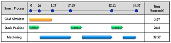
The smart machine tool was possible to finish the preparation in 20 min with four clicks after input 27 3d design files and to run machining process simultaneously with CAM operation as shown in Fig. 6. The CAM and VM time which is run in background simultaneously with stock positioning and machining process is not included to total machining time in case of smart machine tool. So the 4 hours 51 min preparation time is saved compared to experts’ conventional method. An operator fixed electrodes on the table based on the stock position report displayed on the HMI after designs were input. The sizes and positions are measured with OMM in the machine, and working coordinate is automatically set in CNC. The roughing NC data were prepared while the operator was setting stocks, and the machining started without waiting time. Because of limited space of the table, stock positioning and machining process were repeated 3 times. The total fabrication time, including stock fixing, process planning, tool path generation, simulation, and machining was 34 hours 57 min as shown in Table 3.
4.3 Operation Complexity
The automatic machining using a smart machine tool is easy to operate and saves time for machining preparation comparing to conventional machining method of graphite electrode. A trained CAM engineer creates the machining path and the NC operator prepares tools, workpieces, and organizes the order of execution sequence of the numerous NC files to execute the machining. The operation complexity of the experts’ conventional method is about 344 steps as shown in Table 4. Both experienced engineers have a long preparation time and can make mistakes in complex processes.
Comparison of operation complexity
The smart machine tool reduced the operational complexity to 4 button clicks in HMI after drag and drop of 3d model data. 1st AUTO button starts the smart process, 2nd OK button confirms your models, 3rd JIG Ready button confirms after stocks are set on the smart jig, and 4th Auto RUN button starts machining if NC data of first model is generated as shown in Fig. 1 and Table 4. All software processes are run in background to prepare machining during an operator setups workpieces. It is able to automatically find and replace alternate tools without human operation when the tool is broken during the machining process. Thereby, the productivity and quality are only depending on the knowledge of the smart machine tool without considering the skill of the operator.
4.4 Quality
Fig. 6 shows 27 graphite electrodes fabricated automatically by the knowledge of smart machine tool. The quality is related to tool path pattern, tool geometry and cutting condition. The tool path pattern, step interval and tool diameter are selected at CAPP step and the spindle speed and federate condition are regulated in virtual machining step. Experts in the experimented mold company checked the quality of 27 electrodes and decided the quality is same to the parts fabricated by their conventional method except a thin long rib shape.
A lack of knowledge of the smart machine tool can lead to defects in unconsidered geometry. Smart machining for thin and long rib shapes caused poor surface roughness due to tool shaking. In order to improve the machining completeness of the thin and long rib shape, knowledge data were improved to recognize thin and long rib features and to apply different machining processes and machining conditions.
5. Conclusion
As the virtual machining of the digital world is synchronized with the actual machining, the machine tool will become smart to simplify and reduce human mistakes in the complex processes.
A smart machine tool that fabricates graphite electrodes with only 3d model input was developed by the cooperation of process planning, machining simulation, and machine tool making companies. The stock positioning method and HMI integrating software technology is developed in this research.
It reduces the operational complexity to 4 button click after drag and drop of 3d model data to fabricate multiple-number of graphite electrodes. The smart machine tool fabricated 27 graphite electrodes with minimum interference of human in 35 hours.
REFERENCES
-
Altan, T., Lilly, B., Kruth, J.-P., König, W., Tönshoff, H., et al., “Advanced Techniques for Die and Mold Manufacturing,” CIRP Annals-Manufacturing Technology, Vol. 42, No. 2, pp. 707-716, 1993.
[https://doi.org/10.1016/S0007-8506(07)62533-5]

-
Yamazaki, K., Kawahara, Y., Jeng, J.-C., and Aoyama, H., “Autonomous Process Planning with Real-Time Machining for Productive Sculptured Surface Manufacturing Based on Automatic Recognition of Geometric Features,” CIRP Annals-Manufacturing Technology, Vol. 44, No. 1, pp. 439-444, 1995.
[https://doi.org/10.1016/S0007-8506(07)62359-2]
-
Altintas, Y., Kersting, P., Biermann, D., Budak, E., Denkena, B., et al., “Virtual Process Systems for Part Machining Operations,” CIRP Annals-Manufacturing Technology, Vol. 63, No. 2, pp. 585-605, 2014.
[https://doi.org/10.1016/j.cirp.2014.05.007]
-
Denkena, B. and Koeller, M., “Simulation Based Parameterization for Process Monitoring of Machining Operations,” Procedia CIRP, Vol. 12, pp. 79-84, 2013.
[https://doi.org/10.1016/j.procir.2013.09.015]
-
Kim, S., “Integration of Pre-Simulation and Sensorless Monitoring for Smart Mould Machining,” International Journal of Simulation Modelling, Vol. 15, No. 4, pp. 623-636, 2016.
[https://doi.org/10.2507/IJSIMM15(4)4.354]
-
Lee, C.-S., “Tool Path Generation for a Four-Axis Machine to Engrave Letters on Tire Sidewall Molds,” Int. J. Precis. Eng. Manuf., Vol. 10, No. 3, pp. 75-82, 2009.
[https://doi.org/10.1007/s12541-009-0050-z]
-
Ramesh, R., Jyothirmai, S., and Lavanya, K., “Intelligent Automation of Design and Manufacturing in Machine Tools Using an Open Architecture Motion Controller,” Journal of Manufacturing Systems, Vol. 32, No. 1, pp. 248-259, 2013.
[https://doi.org/10.1016/j.jmsy.2012.11.004]
-
Ding, X., Fuh, J., Lee, K., Zhang, Y., and Nee, A., “A Computer-Aided EDM Electrode Design System for Mold Manufacturing,” International Journal of Production Research, Vol. 38, No. 13, pp. 3079-3092, 2000.
[https://doi.org/10.1080/00207540050117459]
-
Schroeter, R. B., Kratochvil, R., and de Oliveira Gomes, J., “High-Speed Finishing Milling of Industrial Graphite Electrodes,” Journal of Materials Processing Technology, Vol. 179, Nos. 1-3, pp. 128-132, 2006.
[https://doi.org/10.1016/j.jmatprotec.2006.03.076]
-
Yang, Y.-K., Shie, J.-R., and Huang, C.-H., “Optimization of Dry Machining Parameters for High-Purity Graphite in End-Milling Process,” Materials and Manufacturing Processes, Vol. 21, No. 8, pp. 832-837, 2006.
[https://doi.org/10.1080/03602550600728141]
-
Yusof, Y. and Latif, K., “Survey on Computer-Aided Process Planning,” International Journal of Advanced Manufacturing Technology, Vol. 75, Nos. 1-4, pp. 77-89, 2014.
[https://doi.org/10.1007/s00170-014-6073-3]
-
Deja, M. and Siemiatkowski, M. S., “Feature-Based Generation of Machining Process Plans for Optimised Parts Manufacture,” Journal of Intelligent Manufacturing, Vol. 24, No. 4, pp. 831-846, 2013.
[https://doi.org/10.1007/s10845-012-0633-x]
-
Wang, L., Wang, W., and Liu, D., “Dynamic Feature Based Adaptive Process Planning for Energy-Efficient NC Machining,” CIRP Annals-Manufacturing Technology, Vol. 66, No. 1, pp. 441-444, 2017.
[https://doi.org/10.1016/j.cirp.2017.04.015]
- Nice Solution Co., Ltd., http://www.ncass.co.kr, (Accessed 24 JAN 2018)
- NCB Co., Ltd., http://www.ncbrain.com, (Accessed 24 JAN 2018)
-
Fussell, B., Jerard, R., and Hemmett, J., “Robust Feedrate Selection for 3-Axis NC Machining Using Discrete Models,” Journal of Manufacturing Science and Engineering, Vol. 123, No. 2, pp. 214-224, 2001.
[https://doi.org/10.1115/1.1365398]
-
Fussell, B. K., Jerard, R. B., and Hemmett, J. G., “Modeling of Cutting Geometry and Forces for 5-Axis Sculptured Surface Machining,” Computer-Aided Design, Vol. 35, No. 4, pp. 333-346, 2003.
[https://doi.org/10.1016/S0010-4485(02)00055-6]
-
Altintas, Y., Spence, A., and Tlusty, J., “End Milling Force Algorithms for CAD Systems,” CIRP Annals-Manufacturing Technology, Vol. 40, No. 1, pp. 31-34, 1991.
[https://doi.org/10.1016/S0007-8506(07)61927-1]
- Ko, J. H., “Plunge Milling Force Model Using Instantaneous Cutting Force Coefficients,” Int. J. Precis. Eng. Manuf., Vol. 7 No. 3, pp. 8-13, 2006.
-
Yun, W.-S. and Cho, D.-W., “Accurate 3-D Cutting Force Prediction Using Cutting Condition Independent Coefficients in End Milling,” International Journal of Machine Tools and Manufacture, Vol. 41, No. 4, pp. 463-478, 2001.
[https://doi.org/10.1016/S0890-6955(00)00097-3]
-
Weinert, K., Enselmann, A., and Friedhoff, J., “Milling Simulation for Process Optimization in the Field of Die and Mould Manufacturing,” CIRP Annals-Manufacturing Technology, Vol. 46, No. 1, pp. 325-328, 1997.
[https://doi.org/10.1016/S0007-8506(07)60835-X]
- Hwacheon Machinery Co., Ltd., http://www.hwacheon.com, (Accessed 24 JAN 2018)
-
Anand, K. V. and Babu, A. R., “Heuristic and Genetic Approach for Nesting of Two-Dimensional Rectangular Shaped Parts with Common Cutting Edge Concept for Laser Cutting and Profile Blanking Processes,” Computers & Industrial Engineering, Vol. 80, pp. 111-124, 2015.
[https://doi.org/10.1016/j.cie.2014.11.018]
- Park J. G., “CAM Automatic Standard System,” KOR Patent, 100985514 B1, 2010.
- Park J. G., “Rib and a Solid Distinction Automated Method Using the Program,” KOR Patent, 101567529, 2015.
- Kim, D. J. and Kim, S. J., “Method for Regulating a Path of an Instrument,” NCB Co., Ltd., No. 100872394, 2008.
- Yum, K. Y., Park, J. Y., and Park, D. Y., “Intelligent CNC Machine Tool with Automatic Processing Function and Control Method Thereof,” KOR Patent, 101257275 B1, 2013.
- Kunnung Co., Ltd., http://www.kumnung.co.kr, (Accessed 24 JAN 2018)