Development of Advertising Accessory with Light Guide for Mobile Devices

Copyright © The Korean Society for Precision Engineering
This is an Open-Access article distributed under the terms of the Creative Commons Attribution Non-Commercial License (http://creativecommons.org/licenses/by-nc/3.0) which permits unrestricted non-commercial use, distribution, and reproduction in any medium, provided the original work is properly cited.
Abstract
This paper presents a development process of an advertising accessory including a light guide to be applied to mobile devices. At first, this research is to design an optical part as a light guide to transmit the light more than 10% of the LED light from mobile devices. Secondly, it presents the mechanical design of the part to be applicable to size changes of mobile devices and to enduring external forces. By using ANSYS and OPTISWORKS, a preliminary design including to tune the applied material properties is performed to prevent from the failure of the component, to maintain the proper pressure for holding mobile devices with different thickness, and to obtain enough optical transmission efficiency. In addition, this paper introduces a manufacturing process for the advertising accessory with a chemical and mechanical polishing. In order to measure the performance of the manufactured accessory, here, measurement devices such as measuring the pressing force, luminance, and illuminance are also designed and fabricated. Several modifications are made for the purpose of improving the measured performance.
Keywords:
Advertising accessory of cellphone, Light guide, Optical transmission efficiency키워드:
핸드폰용 광고 액세서리, 광가이드, 광전달효율1. Introduction
Various advertising methods like TV, radio, print, and the Internet are widely used and the proportion of these advertisements has changed with media trends. According to a survey performed by the Korea Communications Commission (KCC) in 2014, the frequency of using smartphones has increased, while the use of other media such as TVs, PCs, newspapers, and radios has decreased.1 It is also predicted that the advertising market based on the Internet and mobile media will continue to grow solely among the entire advertising market.2
The problem with general mobile advertisings such as search engine marketing, social media targeting, and location-based targeting is that the effect of advertisement is decreasing due to the poor advertisement exposure and relatively high cost. On the other hand, light can stimulate customers strongly and it is a powerful tool in the advertising market. For these reasons, it can be an effective advertisement to develop a low-priced accessory using a light from smartphones.
There are many studies on the opto-mechanical system,3 which focus on optics mounts in optical systems.4,5 Various applications and shapes of light guides using LED lamps are presented by Hewlett Packard corp. and Tessnow.6,7 In this research, we introduce the possibility of an accessory in the point of an industrial application as a cheap accessory applicable to mobile devices as shown in Fig. 1. Even the originality of this paper is a little lacking from an academic point of view, it is believed that this work contributes to the relevant industry by sharing the experience of developing the advertising accessory.

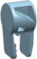
Accessory with light guide for advertising
The purpose of this study is to suggest and develop an accessory, with a light guide to transmit 10% or more light quantity of LED light of a mobile device and a clip-like mechanism to be applicable to the various sizes of the devices whose thickness varies from 6.9 mm to 7.6 mm. In addition, its size is less than 25 mm × 20 mm × 40 mm. In order to achieve these goals, first, the optical design factors are derived and the optical analysis technique is developed. Then, after making a prototype sample, its optical transmission performance is validated experimentally. Second, the clip-like mechanism with enough pressing force for various thickness of the device is designed and manufactured. Third, its manufacturing process consisting of chemical and mechanical process is presented. At last, in order to evaluate its performance, optical (i.e., luminance and illuminance) measurement system and pressing force measurement system are developed.
2. Concept of Light Guiding Accessory
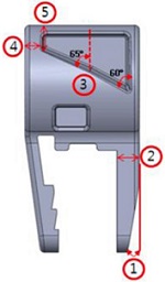
The light guiding accessory is composed of a light guide and a clip-like mechanism as shown in Fig. 2. The light guide consists of two reflection parts and an emitting part. The reflection parts are used effectively to transmit the light from the source of an applied device to the emitting part. The clip-like mechanism has a hinge and tooth-structure. The hinge provides enough flexibility of the light guiding component applicable to the devices with various thickness. The tooth-structure helps grip the mobile device.

Concept of the light guiding accessory with its clip-like mechanism and light guide
In the design of the light guiding accessory, there are some important factors such as the LED light source, the material properties of the light guide, and the reflection angle of the reflection parts. The LED of 0.057 watt is commonly used in mobile devices. The reflection angles of the second reflection part is fixed are 60° and 65°.
To develop the accessory applicable to the 6.9-7.6 mm thickness of the cellphones (FYI, the thickness from iPhone 5s to iPhone 8+ is between 6.9 mm and 7.6 mm), it should have a sufficient pressing force even with the minimum thickness of 6.9 mm and it should be applicable to the maximum thickness of 7.6 mm. In addition, it is necessary to design the light guiding accessory not to exceed the maximum allowable stress.
3. Optical Design Procedure of Light Guide
The optical simulation is performed as follows. After modeling using a 3D CAD program, the model is imported from OPTISWORKS, an optical analysis program. Then, the power of the light source and distance between the light source and the light guide are set to 0.057 W and 0.1 mm. When the distance is set to zero, a large simulation error occurs. Therefore, the minimum distance of 0.1 mm is applied for the optical simulation. After defining the optical properties, the 300 million rays for each analysis are used to get accurate results.
3.1 Material of Light Guide
The light guide is usually made of optical grade material. Generally, injection products such as Acrylic, Polycarbonate (PC), Epoxy resin, and glass material with good optical properties are used. It is decided to use a general-purpose plastic resin since it can be manufactured easily in a cheap way. As shown in Table 1, the material properties of general purpose resins which are inexpensive, have excellent optical properties, and can be injection-molded easily are summarized. All materials have similar optical properties. However, for the mechanical properties, the PC is superior to other materials. Therefore, PC is selected as the material of the light guide in this study.

Material properties of general purpose resin
3.2 Reflection Plate
As shown in Fig. 3(a), the light is delivered from the LED source to the emitting part through the light guide with two reflection plates. If the thickness and the reflection angles of the light guide are appropriately selected and designed, even if some portion of the light is diffused outside the light guide medium, the amount of the transmitted light for shining the advertisement part will be sufficient. However, it is difficult to have a sufficient thickness and the optimal angle because of the size limitation of the accessory for mobile devices. Therefore, by applying the reflection plate to the rear side of the light guide, the amount of the transmitted light can be increased. As shown in Table 2, a color of the first reflection plate for high reflectance is selected as white.

Light guide of the accessory (Sample B-2)s
Reflectance according to reflector color
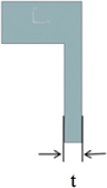
3.3 Thickness of Light Guide
The thickness of the light guide is limited to less than about one-third of the thickness of the general cellphone, generally less than 3 mm, not to feel a foreign body sensation. The optical analysis is performed for 1.5 mm, 2.0 mm, and 2.5 mm cases. Table 3 shows the luminance for each thickness of the light guide. A thickness of 2.5 mm is selected to have a higher luminance while satisfying the aforementioned conditions.
Luminance according to thickness of light guide
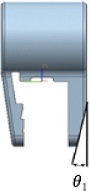
3.4 Reflection Angles
The reflection angle of the first plate in the light guide is one of the major factor for changing the light path on the light guide medium to a desired direction. For the optical analysis, the reflection angle (θ1) is changed to 0, 3, 6, 9, 12, 15 degrees and the luminance is calculated when the light guide thickness is set to 2.5 mm.
Table 4 shows that the higher reflection angle causes the higher luminance. However, for a reflection angle of 12 degrees or more, it was difficult to maintain the mold shape at the 2.5 mm thickness of the light guide. Therefore, the first reflection angle (θ1) is determined as 9 degrees.
Luminance according to reflection angle of light guide
The reflection angle of the second plate is an important factor for changing the light path to the emitting part. As shown in Fig. 4, the luminance of the second plate with two angles, 60° and 65°, is higher than that of the second plate with a single angle, 60°. The optimization of this reflection angle will be performed in a near future.

Luminance according to reflection angle of second plate: (a) 60°, (b) 60°, and 65°
3.5 Development of Measurement Equipment to Test Performance of Accessory
In order to determine the performance of the fabricated accessories, measurement systems to measure the pressing force, luminance, and illuminance are proposed and fabricated.
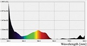
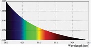
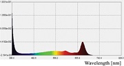
For the purpose of measuring the luminance of developed accessories, a system with a luminance meter (SM208 manufactured by Sanpo Inc.) is developed as shown in Fig. 5(a)8. A smart phone can be fixed by using a clamp and its advertising accessory can be aligned to the center of the luminance sensor at a distance of 40 mm for the measurement. For the illuminance system, an illuminometer (Testo 540 manufactured by Testo Inc.) is installed as shown in Fig. 5(b).

(a) Luminance measurement system, (b) Illuminance measurement system
A cellphone and the developed accessory in a clip-like structure are fastened each other. Therefore, it is necessary to maintain a certain pressure to prevent from the separation. In order to determine whether there is sufficient pressing force or not, a force measurement system (DS2-50N manufactured by OPTECH Inc.) is proposed as shown in Fig. 6.

Pressing force measurement system
The developed accessory is to promote a company’s character or logo. For example, when the LED on your cellphone works for an alarm, the accessory also blinks for advertising. By developing a simple iOS application, its function is tested as shown in Fig. 7.

Operating final samples using test application
3.6 Prototype Fabrication for Optical Design Verification
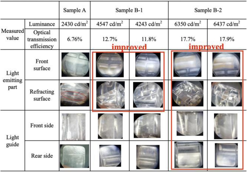
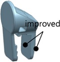
In order to verify the results of the light guide design from the optical analysis, a sample A is fabricated. However, the luminance of the sample A is lower than the expectation. After investigation of the possible reasons, the other samples B-1 and B-2 are fabricated and their improved performances are tested.
From the optical analysis, its luminance and optical transmission efficiency are estimated as 5,097 cd/m2 and 14.37%. However, after the sample is fabricated, the measured luminance and the optical transmission efficiency are 2430 cd/m2 and 6.76%. This value is lower than the development target which is 10%. There is a big difference between the estimated luminance and the measured one. This luminance reduction is expected due to the machining error of the sample, the differences in material properties of the PC, and the surface roughness from machining process.
Table 5 shows dimensional measurement data of the sample A. In order to investigate luminance reduction due to the machining dimensional error, the CAD model is updated based on the measurement data in Table 5 and its optical analysis is conducted again. With the correlated model, the luminance is estimated as 4875.5 cd/m2 which is a little closer to the measured one (i.e., 2430 cd/m2). However, there is a still big discrepancy between measured value and estimated one.
Dimensional measurement data of the sample A
As shown in Table 6, there are some differences in the optical material properties of the PC measured by Korea Polymer Research Institute and used in the OptisWorks library. After updating the optical material properties to the measured values, the luminance is estimated as 4421.3 cd/m2.
Optical properties of PC
Fig. 8 shows the surface roughness status of the sample A. The surfaces of the light guide parts and the front light emitting part are rough. In addition, there is also a machining error on the reflecting surface in Fig. 8. These lead to diffuse reflection, which may be considered to be a cause of luminance reduction. In order to verify this effect, additional samples with improved surface roughness are produced.

Surface roughness of sample A
The surface roughness of the sample A is improved by lapping the light emitting part and machining the reflecting surface precisely as shown in Table 7. The lapping process is a mechanical precision finishing operation with a compound paste, PiKAL 5000#, in an hour to improve the surface roughness. This is called sample B-1. In addition, sample B-2 is produced by lapping the light guide part to improve its roughness and changing its structure to suppress diffuse reflection. All samples are made in duplicate to verify the reproducibility. For the purpose of improving gloss and transparency of the component, the sample B-2 is fabricated by being dipped into 70-80% chloroform solution at 100°C for about 3-4 sec. Fig. 9 shows the manufacturing process with the mechanical and chemical treatments.
Surface roughness and measured optical values of sample

Manufacturing process of samples
Table 8 shows the measured luminance and the optical transmission efficiency are dramatically improved. Therefore, it can be concluded that the surface roughness is a major factor in the luminance. Ten final samples are produced for final confirmation of productivity and optical quality. As a result, it is found that all samples satisfy the performance goal (i.e., optical transmission efficiency is 10% or more) as shown in Table 9.
Luminance and optical transmission efficiency according to each sample
Measured optical properties of final samples
4. Mechanical Design Procedure Applicable to Various Thickness
4.1 Prototype Fabrication for Mechanical Design Verification
The structural FE simulation is performed as follows. After modeling using a 3D CAD program, the model is imported from the structural analysis program, ANSYS. For the mesh procedure, the relevance center is set to fine and mesh size is 0.1 mm which is small enough for accurate results. To obtain the maximum stress, a fixed support boundary condition is applied to the fixed surface and the von-Mises stress is calculated by applying an expansion amplitude of 2 mm which is the same condition in the experiment.
The sample A is fabricated to verity the design result. Table 10 shows simulated and measured results of pressing force and exerted stress. The results in Table 10 satisfy the design criteria such as its size requirement, the pressing force, and the allowable maximum stress. In the cases of the maximum stress, it is difficult to measure with the current measurement system, therefore, it is determined whether there is damage or not when 2 mm of expansion amplitude is applied to the end of the light guide. For further verification, sample B-1 and B-2 are fabricated additionally. Sample A and B meet the design criterion and the difference between the simulation and measurement is within 10%. The pressing force drop of sample B-1 and B-2 is caused by machining error of the light guide. In the final sample fabrication, this machining error is fixed and the pressing force is improved as shown in Table 10.
Simulated and measured results of pressing force and exerted stress
5. Conclusion
For the purpose of developing a cheap and durable optomechanical component to transmit 10% or more light quantity of LED light and be applicable to the 6.9-7.6 mm thickness of a mobile device, the optical and mechanical analysis techniques were applied to the several candidates. Then, after fabricating samples for the validation, they were validated in an experimental way. In order to measure the performance, optical measurement systems and pressing force measurement system were developed. As a result, the optical transmission efficiency of the final samples was 16.5 % and its pressing force was 8.97 N which is considered a sufficient force to hold a cellphone. In addition, with the 2 mm expansion force, the developed accessary was not damaged. Finally, an iOS application was developed to test the developed accessary.
Acknowledgments
This work is done as a part of BK21 Plus and is supported by Academic Promotion System of Korea Polytechnic University. In addition, it is also supported by the National Research Foundation of Korea (NRF) funded by the Ministry of Education (Grant Nos. NRF-2017R1A6A1A03015562 and NRF-2017R1D1A1B03035405). Plus, this research was conducted under ‘the Competency Development Program for Industry Specialists’ of the Korean ministry of Trande, Industry and Energy (MOTIE), operated by Korea Institute for Advancement of Technology (KIAT). (HRD program for P00020007)
REFERENCES
- The Korea Communications Commission, “Broadcast Media Usage Behavior Report 2014,” http://media.nodong.org/bbs/download.php?table=bbs_9&idxno=113393_2&file_extension=pdf&filename=3-3-2014_%B9%E6%BC%DB%B8%C5%C3%BC%C0%CC%BF%EB%C7%E0%C5%C2%C1%B6%BB%E7.compressed.pdf&downCount=7, (Accessed 26 APR 2019) (in Korean)
- Korea Publishing Culture Association, “Advertising Market,” https://terms.naver.com/entry.nhn?docId=2274311&categoryId=55610&cid=55608, (Accessed 26 APR 2019) (in Korean)
- Kim, S. K., Yoo, Y. E., Seo, Y. H., Jae, T. J., Whang, K. H., et al., “Fabrication of Ni Stamper Based on Micro-Pyramid Structures for High Uniformity Light Guide Panel (LGP),” Journal of the Korean Society for Precision Engineering, Vol. 23, No. 9, pp. 174-178, 2006.
-
Ahmad, A., “Handbook of Optomechanical Engineering,” CRC Press, 1996.
[https://doi.org/10.1201/NOE0849397530]

- Yoder, P., “Optomechanical Design in Five Easy Lessons,” http://spie.org/news/optomechanical-design-in-five-easy-lessons?SSO=1, (Accessed 25 APR 2019)
- Packard, H., “Light Guide Techniques Using LED Lamps, Application Brief I-003,” http://www-eng.lbl.gov/~shuman/XENON/REFERENCES&OTHER_MISC/Lightpipe%20design.pdf, (Accessed 25 APR 2019)
-
Tessnow, T., Johnson, R., and Tucker, M., “Application of Led Light Sources with Light Guide Optics,” SAE Technical Paper, 2007-01-1041, 2007.
[https://doi.org/10.4271/2007-01-1041]
- RBK EMD Co., Ltd. and Korea Polytechnic University Industry Academic Co., “Apparatus for Inspecting Light of Portable Device,” KR Patent, No. 1020150146398A, 2015.

Assistant Professor in the department of mechatronics engineering, Korea Polytechnic University. His research interests include the design of a high-performance mechatronics system
E-mail: khkim12@kpu.ac.kr

Assistant Professor in the department of mechanical engineering, Korea Polytechnic University. His research interests focus on development of ultrasonic signal-processing techniques for non-destructive evaluation and finite element analysis of mechanical systems.
E-mail: jeep2000@kpu.ac.kr