
A Method to Investigate Mechanical Properties of Lattice Structures for Additive Manufacturing
1University of Science and Technology, The University of Danang, 54 Nguyen Luong Bang, Lien Chieu District, Danang, Vietnam, 550000
Copyright © The Korean Society for Precision Engineering
This is an Open-Access article distributed under the terms of the Creative Commons Attribution Non-Commercial License (http://creativecommons.org/licenses/by-nc/3.0) which permits unrestricted non-commercial use, distribution, and reproduction in any medium, provided the original work is properly cited.
Abstract
The manufacturing technologies have undergone significant innovation at the beginning of this century from the development of science and technology. One of the most important inventions in manufacturing technologies is the creation of additive manufacturing technology. Additive manufacturing technologies allow building of a 3D object by adding ultra-thin layers of 2D cross-sectional slices of materials upon these previous layers. The most crucial effectiveness of additive manufacturing technologies is to fabricate the complex geometry of products. As a result, the lattice structure is used extensively in industrial product design to minimize usage of materials and reduce the weight of products. However, the simulation to investigate the mechanical properties of the lattice structure in the design space of a product has many issues such as calculation time, memory-consuming, etc. Thus, the paper presents a new method to automatically generate a geometric model of the lattice structure in a computer-aided design environment. This model will be used to make a simulation using the finite element method analysis to investigate the mechanical properties of each configuration of the lattice structure.
Keywords:
Additive manufacturing, 3D printing technology, Lattice structure, Lightweight structure1. Introduction
Today, computers have become very popular and useful tools to support product design activities thanks to the development of science and technology. Product designers can build the 3D geometric model of a product quickly due to the computer-aid design environment. Most simulations to verify the durability and mechanical properties of the designed product are based on this model. After completing the design of the product model on the computer, the product designer will then work with manufacturing process engineers to select the appropriate manufacturing process and technology to produce the design product. The requirements on time for designing and manufacturing the product have to be reduced and shortened in the context of global economic integration. Especially, the quality and cost of the product are two important factors that determine the success of the designed product in the market. Therefore, product designers are always looking for the way to design a product using the least material as possible, but the durability and mechanical properties of the product are still ensured. Moreover, it is necessary to select the appropriate manufacturing process to be able to fabricate the product quickly. One of the solutions to reduce the usage of the material is to use a lattice structure to replace the solid material of the product. Using the lattice structure instead of the solid material inside the product space can make it impossible to manufacture by traditional manufacturing technologies such as casting, forging, stamping, turning and milling. However, the appearance of additive manufacturing technologies can solve all the disadvantages of the traditional ones. The lattice structure can be manufactured quickly by additive manufacturing processes.
Additive manufacturing (AM) is a scientific term to describe manufacturing technologies developed from Rapid Prototyping technologies in the 1980s. The basic principle of the additive manufacturing process is to cover each thin layer of material upon others until to form the final product. Thus, these technologies allow building a 3D geometry model of a product by slicing it into very thin layers of two-dimensional cross-sectional slices. The additive manufacturing technologies can be divided into seven different categories:
- · VAT Photopolymerization
- · Binder Jetting
- · Material Jetting
- · Material Extrusion
- · Powder Bed Fusion
- · Sheet Lamination
- · Directed Energy Deposition
The most important effectiveness of AM technologies is able to manufacture any complex geometry of the product. As a result, the lattice structure is capable to be manufactured. It is used extensively in the industrial product design to minimize the usage of materials and reduce the weight of the product. The lattice structure is applied in many industrial applications on the improvement of durability and mechanical properties of the material,1,2 thermal engineering,3 biomedical engineering.4
A lattice structure is a set of bars connecting each other in order to create a unified structure in the design space. The lattice structure can be categorized into two types as periodic and non-periodic structure. The periodic lattice structure consists of a unit cell structure repeating systematically along to three directions of the coordinate system. The structure of unit cells can have different configurations and they are mentioned in.5 An example of the periodic lattice structure is shown in Fig. 1 with the octet-truss unit cell. The non-periodic lattice structure is created by the bars linking with each other freely without unit cell structure. The length and radius of the bars are totally different in a volume of the non-periodic lattice structure. An example of the volume of the non-periodic lattice structure is given in Fig. 2.

A volume of the periodic lattice structure with unit cells repeating along to three directions

volume of the non-periodic lattice structure
There are many studies to create a volume of the periodic lattice structure in the computer-aided design environment.6-9 The proposed methods can help the product designer integrating the lattice structure into a space of the product quickly. As a result, the geometric model of product with the lattice structure can be created in any commercial computer-aided design software. The product designer can use the lattice structure replacing the space of solid material of the designed product. The usage of material to manufacture the designed product can be significantly reduced by the lattice structure. However, replacing the solid material by the lattice structure can make the designed product at risk of not meeting its durability and mechanical properties. Thus, the important research questions have to be considered:
- · How to replace the solid material by the appropriate lattice structure?
- · How to investigate the durability and mechanical properties of the product with the lattice structure?
In order to find out the answers to these questions, there are some studies to investigate the mechanical properties of the lattice structure by using the finite element method.10-12 The authors in these studies directly use a volume of the 3D geometric model of the lattice structure to make FEM analysis, so the number of elements is very large, and the time of calculation is also very high. In addition, the value of the radius and type of unit cell of the lattice structure are fixed, so it is very difficult to establish the factors of mechanical properties and the radius.
Therefore, the paper presents a new method to investigate the durability and the mechanical properties of different configurations of the periodic lattice structure and to find a relationship between the factors of mechanical properties and the radius of the bars in the lattice structure. The proposed method can reduce the time of calculation comparing to the other methods.
2. Method Description
The paper proposes a method that focuses on studying the mechanical properties of the periodic lattice structure. The geometric model of the periodic lattice structures is built by a set of unit cell structure. The unit cell structure includes the bars connecting each other. The unit cell structure will be repeated in three directions according to the coordinate system. The geometric model of the periodic lattice structure created in the CAD environment will be used to consider the mechanical properties using the finite element method. These approaches have a big limitation in the meshing step because of the size and the number of elements. Each unit cell structure has many bars linking with the others. The size of the unit cell is very small compared to the volume of the lattice structure. The number of unit cell structure in the volume of the lattice structure is very large. The number of elements will be increased if the geometric model of the lattice structure in CAD is used. Therefore, the new approach is mentioned in the paper in order to reduce the number of elements and then the time of calculation will be decreased. Moreover, this approach allows us to change the radius of each bar in the volume of the lattice structure. As a result, a relationship between the factors of its mechanical properties can be established. This result can help the product designer to have the appropriate selection of the unit cell structure of the lattice structure to replace the solid material space.
The method proposed in the paper can be divided into two steps including the generation of the periodic lattice structure and the simulation of mechanical properties using the finite element method. The first step is to create a geometric model of the periodic lattice structure and then the finite element method is used in step two in order to investigate the durability and the mechanical properties of the lattice structure with the different radius of bars.
2.1 Generation of Lattice Structure
A lattice structure can be considered as a hierarchy of different unit structure elements. The studies to generate the geometric model of the periodic lattice structure are mentioned in.5,8,13 However, these proposed methods are to create a 3D model geometric of the periodic lattice structure from the different configuration of the unit cell structure element. This model has many limitations when the finite element method is used to analyze the durability and mechanical properties of the lattice. Therefore, the paper proposes a new approach to generate a geometric model of the periodic lattice structure based on the abstract model of the unit cell structure.
The 3D geometric model of the unit cell includes a set of bars connecting with each other as given in Fig. 3. The geometric crosssection of the bars in the unit cell can be round, rectangular, triangular or any shape. This cross-section is extruded along a line or a curve to build the bar in the unit cell structure. Therefore, the abstract model of the unit cell structure based on two basic geometric elements is the points and the lines.

Configuration of the 3D model of the unit cell structure
The configuration of several unit cells modeled by the abstract model is shown in Fig. 4. The abstract model of a unit cell structure consists only the points and the lines connecting between two points. As a result, the abstract model of a volume of the periodic lattice structure will be generated by the abstract model of the unit cell structure. A volume of the periodic lattice structure is built by the following steps:

Configuration of the abstract model of the unit cell structure
· Step 1: Creation of a row of the unit cell
After choosing a configuration of the unit cell structure as called the basic unit cell, the abstract model of a row of the unit cell is created by moving the basic unit cell along one direction. The abstract model of a row of the octet-truss unit cell is shown in Fig. 5. There are overlapping points and lines between two adjacent unit cells. These points and lines of the behind unit cell will be replaced by the points and lines of the front one.

A row of the octet-truss unit cells.
· Step 2: Creation of a layer of the unit cell
The abstract model of a row of unit cells is used to generate a layer of unit cells by moving the row along the direction. The abstract model of a layer of the octet-truss unit cell is given in Fig. 6. There are obviously the overlapping points and lines between two adjacent rows. These points and lines of the behind row will be replaced by the points and lines of the front one respectively.

A layer of the octet-truss unit cells
· Step 3: Creation of a volume of the unit cell
The abstract model of a layer of unit cells is used to build a volume of unit cells by moving the layer along the direction. The abstract model of a volume of the octet-truss unit cell is shown in Fig. 7. There are also overlapping points and lines between two adjacent layers. These points and lines of the behind layer will be replaced by the points and lines of the front one respectively.

A volume of the octet-truss unit cells
· Step 4: Creation of the lattice structure in design space
A model of a volume of the periodic lattice structure is created in step 3 as a cube space. In order to create the periodic lattice structure inside product space, it needs to embed the volume of the periodic lattice structure into design space in the product by removing the volume outside of the design space as shown in Fig. 8.

A volume of the octet-truss unit cells in the design space
2.2 Finite Element Analysis
The lattice structure is used a lot in product design to replace the space of the solid material in order to reduce the material and the light weight of the product. However, when the lattice structure is used to replace the solid material, there is a risk of making the designed product not to meet fully the durability and mechanical properties. Therefore, it is very necessary to investigate the durability and mechanical properties of the lattice structure with each configuration of the unit cell structure.
There are some experimental studies to consider the durability and the mechanical properties of the lattice structure, but these studies are obviously costly and time-consuming.12-14 Especially, it is very difficult to investigate different configurations of the unit cell of the lattice structure. In addition, there are studies to analyze the durability and mechanical properties of the lattice structure based on numerical simulation using the finite element method.6,11,15,16 Most of the studies use the 3D geometric model of the lattice structure to make simulation using meshing method. However, a volume of the lattice structure includes many unit cells and each unit cell contains several bars connecting each other. The geometric model of the lattice structure is very complex. The more complicated lattice structure and the smaller cell size result in the more slower calculation time because there are many solid elements for this analysis.
As a result, the paper proposes a method that allows investigating the durability and mechanical properties of the lattice structure. The overview of the proposed method is shown in Fig. 9. This method inherits the abstract model of the lattice structure presented above and uses the finite element method to make the analysis and simulation. The outstanding advantage of the proposed method is the calculation time and to be able to establish the relationship between the factors of analysis and radius of the bars of the lattice structure. The proposed method includes the following steps:

An overview of the proposed method
· Step 1: Import data of the abstract model of lattice structure
An abstract model of the lattice structure is generated by the method presented above. The data of this model including the coordinates of points and the line connecting between two points. The data will be then used to define the node and the beam elements in the finite element method.
· Step 2: Build FEM model
After the geometric model for the finite element analysis is built, the beam section will be then defined by the initial value of the radius of the beam. The material property, boundary conditions and loads are also defined in this step.
· Step 3: Run finite element analysis
After the definition of the FEM model is completed, the calculation kernel is used to determine necessary results. When the calculation is finished, the radius of the beam section will be increased by an amount equal to the incremental step of the radius. The calculation will be repeated until the radius of the beam section is equal to the maximum value. The data of all the results of the calculation will be stored.
· Step 4: Result processing
The data of the finite element analysis are used to find the relationship between the factor of mechanical properties and the radius of the bars of the lattice structure will be established by the data processing.
3. Case Study: Relative Stiffness and Maximum Stress Analysis in Abaqus
In order to illustrate the proposed method to investigate the mechanical properties of the lattice structure, the different configurations of unit cell structure as the cube, octet-truss, octahedron, octahedron-cross and open-cell structure shown in Fig. 2 are mentioned in this case study. The abstract model of the periodic lattice structure of each unit cell structure will be created. The data of the abstract model including coordinate points and lines connecting between two points is used in Abaqus software to make a FEM analysis on compression, shearing, torsion, and bending test.
3.1 Generation of Lattice Structure
The Python programming language is used to develop a program to generate a volume of the periodic lattice structure with the proposed configurations of unit cell structure. The pseudocode algorithm of the program is given in Fig. 10. The procedure LatticeGeneration needs to have the input parameters such as the coordinates of points and lines connecting between two points of the unit cell, the number of unit cells along direction X, Y and Z. In the procedure LatticeGeneration, there is another procedure increase to change the index of two points in the lines.

The pseudocode algorithm to generate a volume of unit cells
The 5 × 5 × 5mm3 and 30 × 3 × 3 mm3 volume of five configurations of unit cells are generated using the developed program as shown in Figs. 11 and 12. The data of the volume including the coordinates of points and line connecting between two points are stored in data files. These data files are used to import the data into Abaqus software to make the FEM analysis.

The 5 × 5 × 5 mm3 volume of the lattice structure with the different configurations of the unit cell

The 30 × 3 ×3 mm3 volume of the lattice structure with the different configurations of the unit cell
3.2 Finite Element Analysis in Abaqus
An interface is developed in the commercial software ABAQUS v6.12 by using the Python programming language in order to import the data of the abstract model of the lattice structure with five configurations of the unit cell. The pseudocode algorithm of the interface is given in Fig. 13. The interface allows automatically defining the nodes of the beam elements and creating the beam elements for each bar of the lattice structure from the data of the abstract model. The material, the radius of the beam is varied easily during the FEA analysis. This interface can extract all necessary results of FEA calculations in order to analyze the mechanical properties of different configurations of unit cell structure. Moreover, this interface allows changing automatically some parameters of the model during finite element analysis.

The pseudocode algorithm to run FEA in Abaqus
In the case study, the titanium material is used in the analysis with Young’s modulus E = 110 GPa, Poisson’s ratio ν = 0.315. All beams of the lattice structure are meshed by the B32 element (3-Nodes Quadratic Beam Element). Four tests are proposed for five different configurations of the unit cell structure to analyze the mechanical properties of the lattice structure in a different type of loadings. The stiffness factor and Von-Mises stress are chosen to compare the performance of different configurations of the unit cell structure. The stiffness of the lattice structure represents the potentiality to resist the deformations of the structure in response to an applied force. It depends on the material, the shape of the structure and the boundary conditions. In the case of shearing test, the shearing stiffness is calculated from the ratio of applied force and shear deformation.
A compression test is considered to compare the stiffness of these cells. A shearing test to evaluate the stiffness and the distribution of stress in the bars of the lattice structure. The bending and torsion test are proposed in the case of complicated loading. The relative stiffness coefficient is defined as the ratio between the stiffness of the volume of the lattice structure and the same volume of the solid material. This coefficient is used to compare the mechanical properties of five types of the lattice structure.
3.3 Finite Element Simulation Results and Discussions
In this case, the volume of lattice structure will be investigated on compression, shearing and bending test. Each point in the data of the lattice structure will be considered as a node in the bar element of the finite element method. Each beam element is defined by the start and end point in the data of lines of the lattice structure. The boundary condition and the load are automatically defined using the extracted data in the volume of the lattice structure. A program using python language is developed in Abaqus in order to calculate some factors of the mechanical properties as the stiffness, the maximum stress.
This program permits to change the value of the radius of each bar. As a result, the relationship between the factors and the radius of the bar can be established. The results of displacement distribution of each bar in the compression simulation are given in Fig. 14. The other results of the different simulations are given in the appendix.

The results of displacement distribution in compression simulation with the determined radius value of the bar
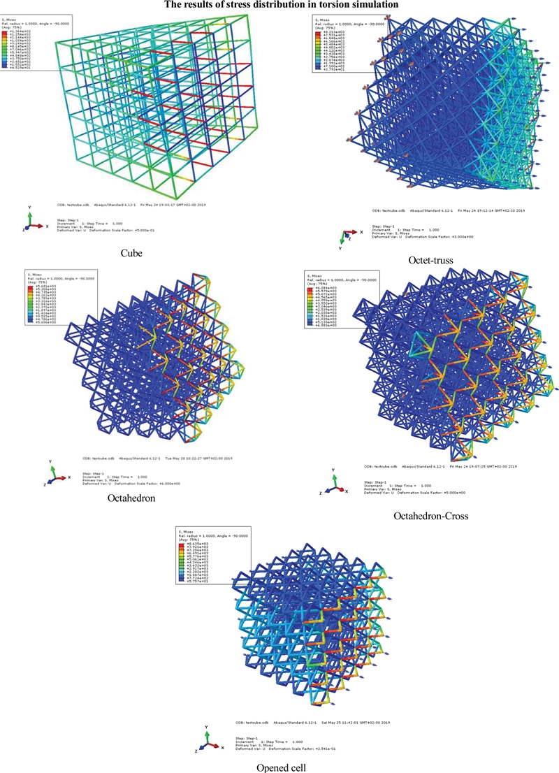
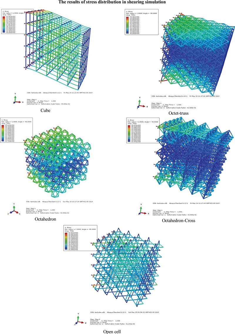
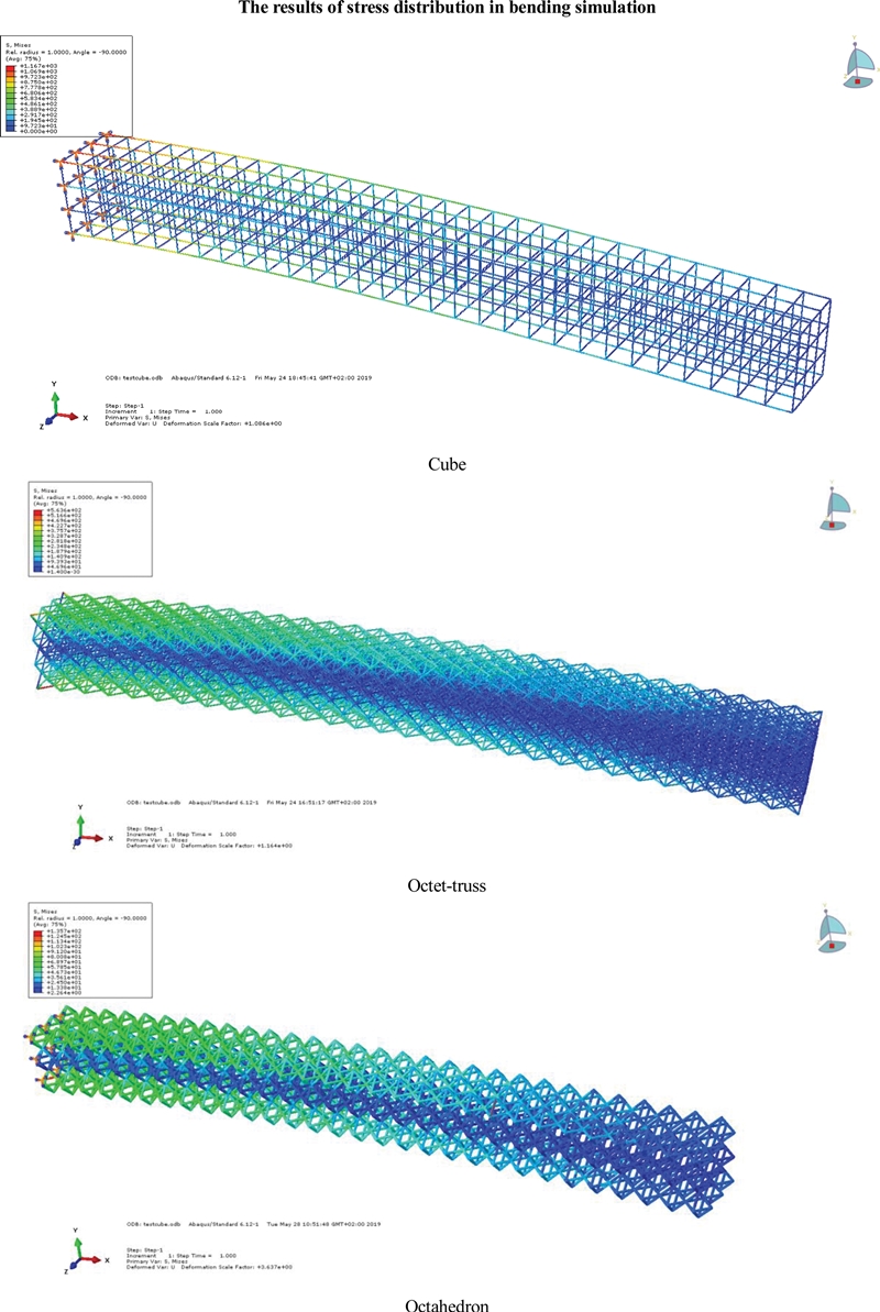
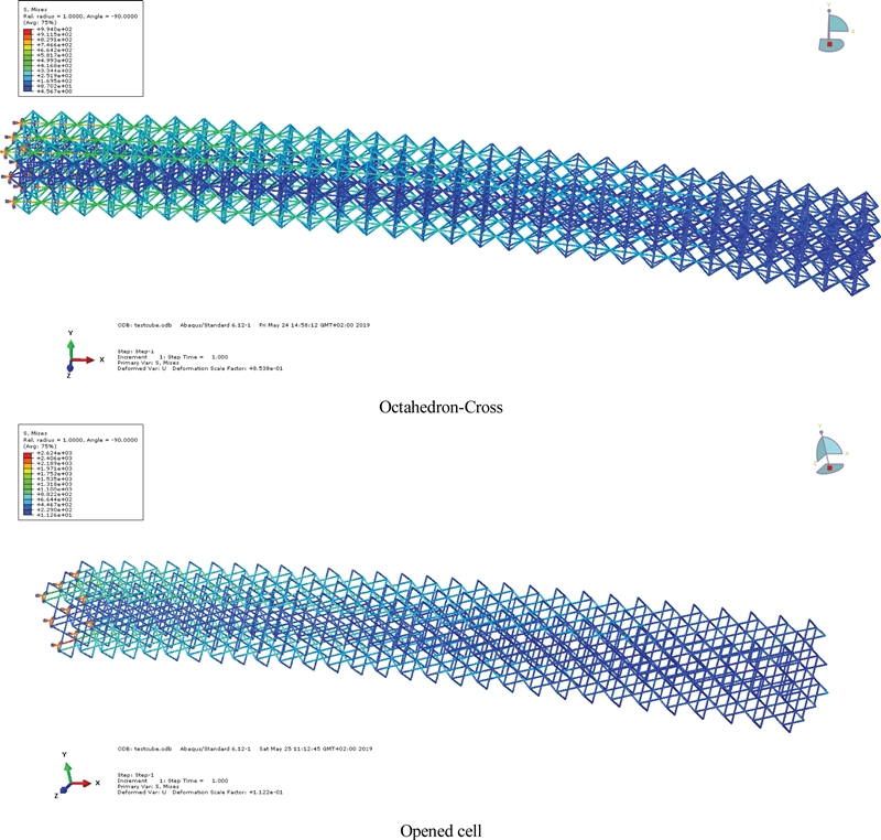
The relationship between the factors and the radius of the bars can be established based on the results of the simulation. The relationship between the stiffness, the maximum stress of five configurations of the unit cell and the value of the radius of the bar in compression, shearing, torsion, and bending test is shown in Figs. 15-18 respectively. In general, a volume of the lattice structure with the octet-truss unit cell structure has the best stiffness according to the value of the radius of the bars for different tests. Obviously, the octet-truss unit cell structure has 24 bars connecting each other and it has the most connecting bars compared to the other configuration of the unit cell structure. Therefore, it has the best stiffness in the compression, shearing, torsion and bending test. The mechanical properties of the lattice structure with the open-cell unit cell structure are the weakest in comparison with the others. It is also reasonable because this unit cell structure has only 8 bars connected to each other. The inappropriate arrangement of bars in open-cell unit results logically in the lowest stiffness and the highest stress distribution in each bar although the radius and the density increase in this unit.

The results of the maximum stress and the stiffness in the compression test

The results of the maximum stress and the stiffness in the shearing test

The results of the stiffness in the torsion test

The results of the stiffness in the bending test
The results in Figs. 15, 16, and 18 show that the maximum stress of the beam elements decreases quickly when the radius of each bar of the unit cell structure is increased. The value of the maximum stress in the bars of the open-cell unit structure is much more than the octet-truss and other unit cells in all cases of loading. The results are very reasonable because the number of bars in the open-cell unit structure is less than other unit cells. Especially, the arrangement of the bars is inherently less stable than other unit cells.
However, if the density of the unit cell structure is considered, the relative stiffness of the volume of the lattice structure of octettruss will be changed in the different tests. In this case, the cube unit cell structure has superior features in comparison with other configurations. The relative stiffness of a volume of the lattice structure with the cube unit cell structure in the compression, torsion and bending test is the best according to the density. The cube unit cell structure should be chosen when the product is applied by compression, torsion or bending load. As a result, the product designer can select the cube configuration of the unit cell structure to design a volume of the periodic lattice structure in order to replace the space of the solid material of the product. The weight of the product can be reduced but the durability and the mechanical properties of the product are still able to be ensured.
In addition, the relative stiffness of a volume of the lattice structure with the octahedron and octahedron-cross unit cell structure is better than octet-truss in the bending and shearing test. Therefore, it is necessary to have a good strategy to select an appropriate unit cell structure to help product designers using lattice structure in design activities.
Moreover, the most important advantage of the proposed method to investigate the mechanical properties of the lattice is the calculation time for each finite element analysis. The calculation time for each run is about 30 seconds and it takes about 10 minutes for total calculation in each test by using a computer Intel Core i5 M460 2.53 GHz with 8 GB of RAM. Thus, the proposed method allows us to consider the mechanical properties of many configurations of the unit cell structure.
4. Conclusion
The paper proposed a new method that allows investigating automatically the mechanical properties of the lattice structure with different configurations of the unit cell structure. The method is based on two approaches. The first approach to generate automatically a geometric model of a volume of lattice structure with different configurations of the unit cell structure. The model includes only the points and the lines connecting between two points in the lattice structure. The second approach aims to import the data of the abstract model of the lattice structure and build automatically the finite element model. The finite element analysis kernel is used to determine factors of the mechanical properties of the lattice structure. The most important advantage of the proposed method is calculation time and the changing radius of the bars of the lattice structure during finite element analysis. As a result, the relationship between the factors of the mechanical properties and the parameters of the lattice structure can be established.
In addition, a case study is mentioned in the paper for analysis of the mechanical properties of the lattice structure with five configurations of the unit cell structure. A program developed in the commercial software Abaqus using Python programming language is to generate automatically finite element simulation on different mechanical properties tests as compression, shearing, torsion, and bending test. The relationship between the stiffness, the maximum stress and the radius of the bars or the density of the lattice structure is established. As a result, the product designer can have a good strategy to select the appropriate configuration of the unit cell structure for replacing the space of solid material.
In future work, the result of finite element analysis will be used to implement a topology optimization for the lattice structure. The goal of the topology optimization is to minimize the mass of the lattice structure but structure, but still ensure the mechanical properties. As a result, the radius of each bar of the lattice structure can be determined.
Acknowledgments
This study was financially supported by University of Science and Technology, The University of Danang under research project (No. T2020-02-01).
REFERENCES
-
Challis, V. J., Xu, X., Zhang, L. C., Roberts, A. P., Grotowski, J. F., et al., “High Specific Strength and Stiffness Structures Produced Using Selective Laser Melting,” Materials & Design, Vol. 63, pp. 783-788, 2014.
[https://doi.org/10.1016/j.matdes.2014.05.064]

-
Shen, Y., McKown, S., Tsopanos, S., Sutcliffe, C. J., Mines, R. A. W., et al., “The Mechanical Properties of Sandwich Structures based on Metal Lattice Architectures,” Journal of Sandwich Structures and Materials, Vol. 12, No. 2, pp. 159-180, 2010.
[https://doi.org/10.1177/1099636209104536]
-
Wong, M., Owen, I., Sutcliffe, C., and Puri, A., “Convective Heat Transfer and Pressure Losses across Novel Heat Sinks Fabricated by Selective Laser Melting,” International Journal of Heat and Mass Transfer, Vol. 52, Nos. 1-2, pp. 281-288, 2009.
[https://doi.org/10.1016/j.ijheatmasstransfer.2008.06.002]
-
Parthasarathy, J., Starly, B., and Raman, S., “A Design for the Additive Manufacture of Functionally Graded Porous Structures with Tailored Mechanical Properties for Biomedical Applications,” Journal of Manufacturing Processes, Vol. 13, No. 2, pp. 160-170, 2011.
[https://doi.org/10.1016/j.jmapro.2011.01.004]
-
Nguyen, D. S. and Vignat, F., “A Method to Generate Lattice Structure for Additive Manufacturing,” Proc. of the International Conference on Industrial Engineering and Engineering Management, pp. 966-970, 2016.
[https://doi.org/10.1109/IEEM.2016.7798021]
-
Azmana, A. H., Vignat, F., and Villeneuve, F., “CAD Tools and File Format Performance Evaluation in Designing Lattice Structures for Additive Manufacturing,” Jurnal Teknologi, Vol. 80, No. 4, pp. 87-95, 2018.
[https://doi.org/10.11113/jt.v80.12058]
-
Gorguluarslan, R. M., Gandhi, U. N., Mandapati, R., and Choi, S. K., “Design and Fabrication of Periodic Lattice-Based Cellular Structures,” Computer-Aided Design and Applications, Vol. 13, No. 1, pp. 50-62, 2016.
[https://doi.org/10.1080/16864360.2015.1059194]
-
McMillan, M., Jurg, M., Leary, M., and Brandit, M., “Programmatic Lattice Generation for Additive Manufacture,” Procedia Technology, Vol. 20, No. Supplement C, pp. 178-184, 2015.
[https://doi.org/10.1016/j.protcy.2015.07.029]
-
Nguyen, D. S., Tran, T. T., Le, D. K., and Le, V. T., “Creation of Lattice Structures for Additive Manufacturing in CAD Environment,” Proc. of the International Conference on Industrial Engineering and Engineering Management, pp. 396-400, 2018.
[https://doi.org/10.1109/IEEM.2018.8607271]
- Azman, A. H., “Method for Integration of Lattice Structures in Design for Additive Manufacturing,” G-SCOP Laboratory, 2017.
-
Abdulhadi, H. S. and Mian, A., “Effect of Strut Length and Orientation on Elastic Mechanical Response of Modified Body- Centered Cubic Lattice Structures,” Proceedings of the Institution of Mechanical Engineers, Part L: Journal of Materials: Design and Applications, Vol. 233, No. 11, pp. 2219-2233, 2019.
[https://doi.org/10.1177/1464420719841084]
-
Geng, X., Lu, Y., Liu, C., Li, W., and Yue, Z., “Fracture Characteristic Analysis of Cellular Lattice Structures under Tensile Load,” International Journal of Solids and Structures, Vol. 163, pp. 170-177, 2019.
[https://doi.org/10.1016/j.ijsolstr.2019.01.006]
-
Beyer, C. and Figueroa, D., “Design and Analysis of Lattice Structures for Additive Manufacturing,” Journal of Manufacturing Science and Engineering, Vol. 138, No. 12, Paper No. 121014, 2016.
[https://doi.org/10.1115/1.4033957]
-
Abueidda, D. W., Elhebeary, M., Shiang, C. S., Pang, S., Al-Rub R. K. A., et al., “Mechanical Properties of 3D Printed Polymeric Gyroid Cellular Structures: Experimental and Finite Element Study,” Materials & Design, Vol. 165, Paper No. 107597, 2019.
[https://doi.org/10.1016/j.matdes.2019.107597]
-
Chen W., Zheng X., and Liu S., “Finite-Element-Mesh Based Method for Modeling and Optimization of Lattice Structures for Additive Manufacturing,” Materials, Vol. 11, No. 11, 2018.
[https://doi.org/10.3390/ma11112073]
-
Helou, M. and Kara, S., “Design, Analysis and Manufacturing of Lattice Structures: An Overview,” International Journal of Computer Integrated Manufacturing, Vol. 31, No. 3, pp. 243-261, 2018.
[https://doi.org/10.1080/0951192X.2017.1407456]
Appendix

Ph.D in Industrial Engineering Department of Transportation and Mechanical Engineering, University of Science and Technology, The University of Danang, Vietnam. His research interest is Additive Manufacturing, Topology Optimization and Manufacturing Design Process.
E-mail: ndson@dut.udn.vn

PhD in Mechanics of Solids Department of Transportation and Mechanical Engineering, University of Science and Technology, The University of Danang, Vietnam. His research interest is Computation Mechanics, Modeling and Simulation Multiphysics Coupled Problems.
E-mail: nvthan@dut.udn.vn