Development of Steering Stop Parts for Automobile Suspension Using Former Cold Forging Complex Forming Technology

Copyright © The Korean Society for Precision Engineering
This is an Open-Access article distributed under the terms of the Creative Commons Attribution Non-Commercial License (http://creativecommons.org/licenses/by-nc/3.0) which permits unrestricted non-commercial use, distribution, and reproduction in any medium, provided the original work is properly cited.
Abstract
Steering Stop parts constituting the suspension system of automobiles are located inside an automobile suspension. They are used to fix upper and lower suspension arm parts by welding. The purpose of this study was to develop Steering Stop parts for automobile suspension. Cost increase due to problem of existing tool life is a challenging issue. This study tries to solve the tool life problem and reduce the cost using a former cold forging complex forming technology. We developed a long-life complex forming technology between multistage former forging and cold forging for producing Steering Stop parts of automobile suspension.
Keywords:
Steering Stop parts, Automobile suspension, Former forging, Cold forging, Complex forming technology1. Introduction
Automobile suspension is a device that prevents damage to the automobile body or lower body and improves riding comfort by preventing the axle from directly transmitting vibrations or shocks received from the road surface to the automobile body when driving by connecting the axle to the automobile body. It is composed of a chassis spring that relieves the shock from the road surface, a shock absorber that improves riding comfort by suppressing the free vibration of the chassis spring, and a stabilizer that prevents the automobile from twisting sideways. In addition, the suspension transmits the driving force generated to the driving wheels or the braking force of each wheel to the automobile body when braking, and at the same time withstands the centrifugal force when turning, and supports each wheel in the correct position with respect to the automobile body. Steering Stop parts are located inside the automobile chassis suspension and are used to fix the upper and lower suspension arm parts by welding. In order to precisely weld the upper and lower parts, gap management is important. It is a part that requires precision because it has to be welded with a constant gap [1].
Springs used for suspension are largely divided into steel springs, rubber springs, and gas springs, and steel springs are further divided into leaf springs, coil springs, and torsion bars. Among them, the coil spring is the most used independent type, and it has the advantage of not occupying much space and not causing an uncertain friction action. Steering Stop parts of automobile suspension are processed by the existing former cold forging, which causes tool life to become a problem, resulting in cost increase and quality problems. As a part, there should be no shape precision and no deformation of the product. Existing complex forging technology is currently being applied to hot forging and cold forging process. However, since hot forging process has poor dimensional precision of the product, it must be formed by a cold process after a hot process to reduce cost and obtain a product with excellent precision [2-5]. Complex forging parts frequently have problems of cost increase and quality deterioration due to tool breakage when working only with the cold process, and cold and hot complex forging technology is applied to solve these problems [6-8].
This study is to develop a Steering Stop parts for a vehicle suspension that applies a long-life former cold forging complex forming technology. As the existing tool life problem persists, quality problems are emerging due to tool replacement and cost increase. This was improved to the 2nd former forging process, the 1st cold forging process, and the 1st trimming process to solve the tool life problem and reduce costs. In the Steering Stop parts, directional work due to symmetry is required for the existing tool, and tool breakage occurs frequently during the cold forging process, and cracks occur in the product exterior. To improve this, the existing former forging of 5 processes and cold forging of 1 process were improved to the former forging of 2 processes, the cold forging process, and the trimming process to improve the life of the tool and reduce the cost. Therefore, comparing the technology development of Steering Stop parts before and after the technology development of the Steering Stop parts, in the past, the former forging of 5 processes and the cold forging process were performed, and tool damage occurred frequently. The process was improved to remove by trimming process. As a result, the tool life was more than doubled compared to the previous one [9-11].
2. Tool Experiment
2.1 Material Property Test
For forming analysis of the Steering Stop parts, a compression test was performed to confirm the mechanical properties. The material used for the test was SWRCH18A, and the test piece was manufactured by wire cutting with a diameter of 10 mm and a height of 15 mm in a cylindrical shape as shown in Fig. 1. The compression test was performed in a 100-ton universal testing machine (UTM) at a test speed of 2 mm/min and a material reduction rate of 60% (9 mm). Fig. 2 shows the compression test equipment, and Fig. 3 shows the specimens before and after the compression test. Fig. 4 shows the compression process of SWRCH18A material as a curve of nominal stress and nominal strain, and a curve of true stress and strain, and the obtained data was applied as material properties for forming analysis.

Test specimen size

Experimental equipment for compression test

Test specimens of before and after compression test

Stress-strain curve of the compression test for SWRCH18A
2.2 Steering Stop Tool Design and Making
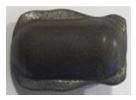
The characteristic of the former forging process is that it is formed by giving a large deformation step by step in the former forging machine. The feature of the cold forging process is that it is formed by giving a large deformation like the former forging process in the forging press, and the processing surface is smooth and the material recovery rate is good because there is no need for post-processing. In addition, the dimensional accuracy of the product is excellent and the mechanical properties by work hardening are improved. The optimal process was designed to develop the Steering Stop parts for automobile suspension by applying the former cold forging complex forming technology that fused former forging and cold forging. The number of forging steps is determined according to the shape of the forging product and the degree of cross-sectional change. Even if the shape is complex and the cross-sectional change is severe, it is better to design as few steps as possible. Fig. 5 shows the Steering Stop model product. Existing Steering Stop parts cause tool breakage and exterior defects due to operator error by directional work, and product defects due to tool breakage in the former and cold forging process. Fig. 6 shows the broken part of the cold forging tool of the Steering Stop parts. The die breakage occurred at the bottom of the die subjected to concentrated stress. In order to improve this, the optimal process was designed and manufactured by applying the former cold forging complex forming technology that combines former forging and cold forging.

3D model of Steering Stop product

Cold forging tool breakage of Steering Stop product before improvement
This Steering Stop parts process consists of a total of 4 processes, designed in the order of 1st step former forging, 2nd step former forging, 3rd step cold forging, and 4th step trimming process. Table 1 shows the process sequence of the Steering Stop tools.

Process sequence of Steering Stop tools
The whole process before improvement consists of a total of 6 processes, the fifth performing former forging, and the final closed cold forging process. In this case, punch and tool breakage due to concentrated load occurred frequently in the 5th process of former forging and the final closed cold forging process. To improve this, the former forging process was simplified to two processes, the closed cold forging process was improved to an open cold forging process, and a final trimming process was added to remove flash. In other words, in order to improve the damage of punches and dies due to concentrated load in the 5th process of the existing former forging process and the final closed cold forging process, edge processing is performed in the former forging process, and a trimming process is added after open cold forging in the cold forging process. Therefore, it was improved to distribute stress concentration between processes.
2nd forging process is shown in Fig. 7, the preform was designed to be Ø 14.2 × 22 mm. Fig. 8 shows the assembly diagram of the cold forging die, and Fig. 9 shows the trimming tool assembly diagram. Cemented carbide was used for the punch material of the 3-step cold forging tool, and SKH55 high-speed tool steel was used for the tool material. The 4-step trimming process was designed to cut the flash generated in the 3-step cold forging process, and STD11 alloy tool steel was used for the punch and tool of the 4-step trimming tool.

Preform shape of Steering Stop

Cold forging tool design of Steering Stop

Trimming tool design of Steering Stop
3. Forming Analysis
The process design was carried out for the production of Steering Stop parts, and after cutting the raw material, the product was designed to be completed by 1st step former forging, 2nd step former forging, 3rd step cold forging, and 4th step trimming. It is designed to carry out 3-step cold forging through annealing, shot peening, and lubrication treatment after 2-step former forging. Forming analysis was not performed in the 1-step former primary forging and 2-step former secondary forging process as it was a process of making a preform, but in the 3-step cold forging process, forging analysis was performed. Steering Stop parts and tools were modeled in 3D using 3D CAD s/w, and forging analysis of Steering Stop tools were performed using simufact forming software. For the forging analysis, the compression test data of SWRCH18A material were input as mechanical properties. Table 2 shows the conditions for forging forming analysis. Forging analysis was performed by dividing the friction coefficients for each process into 0.05, 0.1, 0.15, and 0.2 during cold forging. The forming speed of the forging press was applied at 20 SPM. Fig. 10 shows the part model of the cold forging tool. As a process of making a preform in the former forging process, the preform formed in the former secondary forging process is placed on the lower die and open-type cold forging is performed. Fig. 11 shows the effective plastic strain rate when the friction coefficient is 0.1 in the cold forging process, and Fig. 12 shows the equivalent stress. Fig. 13 shows the maximum load according to the friction coefficient as a result of cold forging analysis. As a result of checking the change in the maximum load according to the change in the friction coefficient, it was found that the friction coefficient was 107 tons at 0.05, 110 tons at 0.1, 115 tons at 0.15, and 118 tons at 0.2. In general, the friction coefficient was performed in four cases from 0.05 to 0.2 based on 0.12 applied during cold forging. According to the friction coefficient, there was little difference in the shape of the cold forging process product, and it was judged to be applicable based on the 250-ton press actually used. In order to prevent tool breakage, the 3-step cold forging tool is an open forging tool, as shown in Fig. 8. Fig. 14 shows the analysis results according to the length of the preform in cold forging. When the length of the preform is 17 mm and 19 mm, the occurrence of pitting is predicted, but when the length of the preform is 22 mm, it does not occur. Fig. 15 shows the defect occurrence site when the length of the preform is 17 mm. The pitting area is predicted at both edges of the Steering Stop parts. It is important to avoid stress concentration in cold forging punches and dies to improve tool life. In the forming analysis result, when the length of the preform is 22 mm, no cracking occurs. Therefore, the preform length was determined to be 22 mm.
Simulation conditions of cold forging

3D model of Steering Stop tool

Effective plastic strain of Steering Stop at friction coefficient 0.1

Equivalent stress of Steering Stop at friction coefficient 0.1

Load change according to friction coefficient

Underfill occurrence according to preform length

Simulation results of underfill defect of Steering Stop product at preform length 17 mm
4. Experimental Results and Discussion
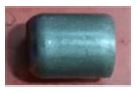
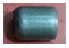
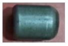
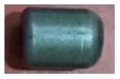
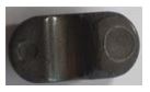
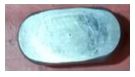
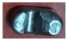
In order to improve the mold life of the Steering Stop parts for automobile suspension, the SWRCH18A round bar material is cut and the former primary forging and former secondary forging are performed to produce a preform, designing the process in the order of cold forging and trimming, and designing and manufacturing the mold Thus, a prototype was produced. Fig. 16 shows the areas where the formation of pitting occurs in the cold forging product. The 3-step cold forging tool is designed as an open forging tool to prevent tool breakage, so it is easy to cause cracking. In consideration of this, the length of the preform was manufactured to 22 mm by referring to the analysis results according to the length of the preform. In particular, since cracks appear at both corners of the product, it is necessary to prevent the occurrence of cracks while improving the life of the tool. Therefore, the length of the preform was determined to be 22 mm in the direction of improving the tool life rather than reducing the material. In order to trim the Steering Stop parts produced in the 3-step cold forging process, the final prototype was obtained from the 4-step trimming tool. That is, by inserting the 3-step cold forging product into the trimming tool installed in the press, the flash generated on the outside was removed. Fig. 17 shows the process product produced in the cold forging tool, and Fig. 18 shows the final prototype produced in the trimming tool. In the actual cold forging test, cracks occurred near both corners of the product as in the forming analysis results. In general, the coefficient of friction in cold forging is evaluated to be about 0.1 to 0.2, but the shape difference in the cold forging process is hardly shown according to the friction coefficient in the forming analysis results. Compared with the analysis results in the actual forming test, the friction coefficient is judged to be about 0.1 to 0.2. A tooled product that satisfies the final dimensional accuracy was manufactured by trimming the Steering Stop process parts secured by the cold forging tool. That is, the trimming tool was able to obtain the final product by inserting the cold forging process product after installing the tool on the 55 ton press. Fig. 19 shows a scene of measuring the outer diameter of a Steering Stop parts for a vehicle suspension. The outer diameter of the Steering Stop product for automobile suspension was measured using a three-dimensional measuring machine. As a result of measuring the outer diameter of 10 prototype samples, the dimensional accuracy was satisfied as 0.168 mm. Table 3 shows the tool life of experimentally produced Steering Stop parts. During product production, it was found that the tool life was improved from about 5,000 pieces using the existing high-speed steel material to about 400,000 pieces by applying the cemented carbide material. In other words, in the cold forging process, the tool life of the existing punch was about 5,000, so cemented carbide was applied to produce about 400,000 products at HRA85 hardness. In the trimming process, more than 400,000 products were produced by applying the punch and tool materials with STD11 alloy tool steel.

Underfill defect of Steering Stop product at preform length 17 mm

Cold forging product of Steering Stop

Final trimming product of Steering Stop

Outside diameter measurement of Steering Stop product
Tool lifespan of Steering Stop product
5. Conclusion
In this study, an improvement process was suggested to improve the tool life by developing a Steering Stop parts for automobile suspension using the former cold forging composite forming technology. In order to apply the former cold forging composite forming method of the Steering Stop parts, material properties evaluation, forging analysis, prototype tool design and production, and prototype performance evaluation were performed. The results of this study are summarized as follows.
(1) In order to understand the mechanical properties of SWRCH18A, the raw material of the Steering Stop parts, a stress-strain curve could be obtained through a compression test, and more accurate analysis results could be obtained by applying it to the forging analysis.
(2) In the cold forging analysis results, it was confirmed that the maximum load increased as the friction coefficient increased, and cold forging was possible with little difference in shape by friction. The degree of cracking was predicted according to the length of the preform. In the forming test, it was confirmed that the Steering Stop cold forging is possible.
(3) For the production of Steering Stop parts, it was designed in 4 processes including former primary forging, former secondary forging, cold forging, and trimming from the existing 6 processes, and the final prototype with excellent dimensional accuracy was secured during the trimming process.
(4) It was confirmed that tool life could be improved by securing cold forging technology for Steering Stop parts for automobile suspension.
REFERENCES
-
Park, D. H., Yun, J. J., Kim, K. Y., (2014), A study on laser welding application of the cowl cross member for ultra-high strength steel, Journal of the Korean Society of Manufacturing Technology Engineers, 23(5), 525-531.
[https://doi.org/10.7735/ksmte.2014.23.5.525]

-
Yoon, J., Lee, S., Jeon, H., Lee, J., (2013), Study on the lubrication characteristics at the elevated temperature in hot forging test with extruded AZ80 Mg alloy, Transactions of Materials Processing, 22(2), 108-113.
[https://doi.org/10.5228/KSTP.2013.22.2.108]
-
Song, S.-E., Kwon, H.-H., (2012), A study on the cold forging development of guide valve for the fuel pressure regulator, Journal of the Korean Society of Manufacturing Technology Engineers, 21(2), 331-336.
[https://doi.org/10.7735/ksmte.2012.21.2.331]
-
Kang, B., Ku, T., (2014), Process modification and numerical simulation for an outer race of a CV joint using multi-stage cold forging, Transactions of Materials Processing, 23(4), 211-220.
[https://doi.org/10.5228/KSTP.2014.23.4.211]
-
Jeon, H., Yoon, J., Lee, J., Kim, B., (2014), Plate forging process design for an under-drive brake piston in automatic transmission, Transactions of Materials Processing, 23(2), 88-94.
[https://doi.org/10.5228/KSTP.2014.23.2.88]
-
Park, D.-H., Kwon, H.-H., (2016), Development of automobile engine mounting parts using hot-cold complex forging technology, International Journal of Precision Engineering and Manufacturing-Green Technology, 3(2), 179-184.
[https://doi.org/10.1007/s40684-016-0023-5]
-
Park, D.-H., Han, S.-C., (2015), Integration forming technology based on cold hot forging of clutch jaw parts for farm machinery, Journal of the Korean Society of Manufacturing Technology Engineers, 24(5), 489-495.
[https://doi.org/10.7735/ksmte.2015.24.5.489]
-
Park, D.-H., Kwon, H.-D., Kwon, H.-H., (2019), Development of cam ring gear parts of large diameter for truck clutch using hot-cold complex forging technology of small bar, International Journal of Precision Engineering and Manufacturing, 20(5), 827-836.
[https://doi.org/10.1007/s12541-019-00100-5]
- Jo, A., Jeong, M., Lee, S., Cho, Y., Hwang, S., (2019), Development of hot and cold forging process for manufacturing a hub of dual clutch transmission, Transactions of Materials Processing, 28(6), 321-327.
- Ju, W. H., Park, S.-Y., (2017), Development of outer support ring using complex forging processes, Journal of the Korea Academia-Industrial Cooperation Society, 18(4), 653-659.
-
Nahrmann, M., Matzenmiller, A., (2021), A critical review and assessment of different thermoviscoplastic material models for simultaneous hot/cold forging analysis, International Journal of Material Forming, 14(4), 641-662.
[https://doi.org/10.1007/s12289-020-01553-0]

Head researcher in Gyeongbuk Hybrid Technology Institute. His research interests are plastic working, sheet metal forming, hot and cold complex forging for automobile parts.
E-mail: pdh@ghi.re.kr

President in Hansung Industry Co., Ltd.. His research interests are cold forging and metal forming for automobile parts.
E-mail: sungcher40@hanmail.net

Researcher in Gyeongbuk Hybrid Technology Institute. His research interest is metal forming technologies for automobile parts.
E-mail: stag875@google.com

Professor in the Department of Mechanical Engineering, Daejin University. His research interest is metal forming technologies for automobile parts.
E-mail: hhkwon@daejin.ac.kr