Press Forming/Drawing Molding in the Radiator Support Mold Process of 440 MPa High Strength Steel Sheets

Copyright © The Korean Society for Precision Engineering
This is an Open-Access article distributed under the terms of the Creative Commons Attribution Non-Commercial License (http://creativecommons.org/licenses/by-nc/3.0) which permits unrestricted non-commercial use, distribution, and reproduction in any medium, provided the original work is properly cited.
Abstract
This study aimed to develop automotive radiator support parts by applying the press forming/drawing mold technology of 440 MPa high-tensile steel sheets. It is intended to develop a shape structure that does not generate shape and positional accuracy, deformation, wrinkles, or cracks by maintaining strong contact surface pressure on both sides of the blank material and freezing elastic recovery stress. Therefore, quality improvement and high productivity were secured by applying the forming/drawing method of high-strength steel sheets to the radiator support parts.
Keywords:
Forming/drawing, Radiator support parts, Automotive, High strength steel sheets, Molding technology1. Introduction
Recently, from the viewpoint of automobile convenience, resource conservation, energy conservation, and global environmental measures, lightweight technology, such as the adoption of high-efficiency drive technology, has become an important key element as a way to improve fuel efficiency of automobiles. However, as new parts such as large-capacity batteries and high-pressure fuel tanks used in eco-friendly electric vehicles and hydrogen vehicles are added, the weight of vehicles has increased, and to overcome this, lighter vehicles are needed. As a way to lighten vehicles, there is a wide range of material choices to not only reduce weight by replacing existing steel materials with lightweight materials such as engineering plastics, fiber-reinforced plastics, and CFRP, but also to maximize the weight-saving effect through optimal design and component integration. However, high-strength steel sheets have many different characteristics in terms of press forming, so technical solutions are required in car seat parts [1-4]. When producing radiator support parts using a conventional drawing method using high-strength steel plate materials, the blanking pressure is controlled to a single padding pressure when the material located on the upper surface of the lower die is contacted by the punch descending from the upper die and flows into the die. Therefore, it is difficult to solve excessive wrinkles, cracks, and springback problems in the product after molding [5-8]. In particular, not only is there a lot of quality variation due to the difference in contact surface pressure between the upper and lower molds, but it is also causing problems with customer delivery and quality due to excessive working hours and low productivity. As a solution, we aim to improve production, quality, and delivery issues by developing a forming/drawing composite mold technology with a double pressure source structure that can increase the contact surface pressure of the upper and lower molds to ensure strong contact with the blank material. As shown in Fig. 1, the radiator support parts that makes up the car body is a radiator support panel component located inside the front bumper of the car body. It is mounted on the car body along with the head light and rises from the front, rear, both sides, and road surface when the car is driven. It is a key component that blocks external air resistance in advance, absorbs shock when colliding with the car in front, and protects the car body and engine. Therefore, positioning accuracy and material rigidity are required due to the special need to protect the engine from external shocks. In other words, radiator support parts use high-strength steel materials with rigidity because they protect the front of the car's engine room in the event of a collision with the car in front while driving and control air resistance and noise generated from both left and right sides and the road surface. However, due to the physical characteristics of high tensile strength and yield strength of high-strength steel materials, it is difficult to control elastic stresses such as excessive springback, cracks, and distortion during press forming operations [9-13].

Radiator support parts
This study aims to develop automobile radiator support parts by applying press forming/drawing composite mold technology of 440 MPa high-strength steel plate. A forming/drawing composite molding method that can strongly maintain the overall contact surface pressure on both the top and bottom of the blank material was designed and manufactured to compare and analyze the occurrence of deformation, wrinkles, and cracks.
2. Material Property Testing
For the molding analysis of the radiator support parts, a tensile test was performed to confirm the mechanical properties. The material used in the test was galvannealed steel (SGARC440), with a thickness of 0.65 mm, and the specimen was manufactured by wire cutting with a width of 25 mm and a gauge length of 50 mm, as shown in Fig. 2. A tensile test was conducted to determine the mechanical properties, and tensile specimens were manufactured in the rolling direction, 45-degree direction, and 90-degree direction. Table 1 shows the tensile test results of SGARC440 material, and Fig. 3 shows the stress-strain diagram of SGARC440 material. SGARC440 material has a yield strength of 383.5 MPa, tensile strength of 497.1 MPa, and elongation of 29.7%.

Tensile test specimens of SGARC440

Mechanical properties of SGARC440

Stress-strain curve of SGARC440
3. Mold Design and Manufacturing
The manufacturing processes of radiator support parts were designed and manufactured in a total of 6 processes, including 1st process Forming & Drawing, 2nd process Trimming, 3rd process Flanging & Restriking, 4th process Piercing & Cutting, 5th process Piercing & Cam Piercing, and 6th process Piercing & Cutting. Table 2 shows the process sequence of the radiator support mold. Process 1 Forming & Drawing is a process of forming and drawing the high-strength steel blank of the radiator support product, and was produced by applying Forming/Drawing composite mold technology. Process 2 Trimming is a process of trimming the exterior of the product, Process 3 Flanging & Restriking is a process of forming and shaping the flange part, and Process 4 Piercing & Cutting is a process of piercing the hole and cutting the exterior. Process 5 Piercing & Cam Piercing is the process of piercing the hole and piercing the side hole, and Process 6 Piercing & Cutting is the final process of piercing the hole of the product and cutting the outside. Fig. 4 shows the mold for the forming/ drawing process of the radiator support parts. The upper and lower molds were designed and manufactured by applying a casting die set. Fig. 5 shows the initial blank of the forming/drawing process of the radiator support parts. Fig. 6 shows the forming/drawing mold structure of the radiator support parts. We manufactured a forming/drawing mold with a double pressure source structure that can increase the pressure of the contact surfaces of the upper and lower molds to ensure strong contact with the blank material. In other words, the double pressure source structure was designed to strongly contact the blank material with the punch, pad, blank holder, and die. As shown in Fig. 6, the double pressure source structure was manufactured to increase the pressure on the blank contact surface of the upper and lower molds. Figs. 6(a) and 6(b) show before and after forming/drawing, Fig. 6(c) shows forming/drawing method.
Process sequence of radiator support die

Forming/drawing mold of radiator support parts

Forming/drawing process blank of radiator support parts

Forming/drawing method for making radiator support parts
4. Forming Analysis
Process design was conducted to produce radiator support parts, and the blank material was divided into process 1 Forming & Drawing, process 2 Trimming, process 3 Flanging & Restriking, process 4 Piercing & Cutting, process 5 Piercing & Cam Piercing, and process 6 Piercing & Cutting. The process was designed to complete the product. For the 1st process Forming & Drawing mold, sheet metal forming analysis was performed. Radiator support parts and molds were modeled in three dimensions using 3D CAD S/W, and sheet metal forming analysis of the radiator support mold was performed using a forming software (Simufact Forming, HEXAGON). For sheet metal forming analysis, tensile test data of SGARC440 material was input as mechanical properties. Table 3 shows the sheet metal forming analysis conditions. When forming a sheet, a forming analysis was performed by dividing the friction coefficient into 0.1 and 0.15. The forming speed of the press was set at 20 SPM, and the initial blank was a rectangular blank (300 × 640 mm). Fig. 7 shows the part model of the forming & drawing mold in the radiator support parts. In the forming & drawing process, a forming analysis was performed by applying a double pressure source structure to ensure strong contact with the blank material using punches, pads, blank holders, and dies, and to increase the pressure on the contact surfaces of the upper and lower molds.
Simulation conditions of radiator support parts

Forming/drawing mold model of radiator support parts
Fig. 8 shows the thickness change at a friction coefficient of 0.1 as a result of sheet forming analysis of the Forming & Drawing mold, and Fig. 9 shows the thickness change at a friction coefficient of 0.15. In the forming & drawing process, a double pressure source structure is applied to increase the pressure on the contact surfaces of the upper and lower molds, such as punches, pads, blank holders, and dies, allowing strong contact with the blank material, resulting in a significant decrease in thickness in areas where stress is concentrated. As a result of checking the thickness change according to the friction coefficient change, when the friction coefficient is 0.1, the thickness is at least 0.44 mm, when the friction coefficient is 0.15, the thickness is at least 0.36 mm, etc. It can be seen that the thickness reduction increases as the friction coefficient increases.

Thickness change of radiator support parts at friction coefficient 0.1

Thickness change of radiator support parts at friction coefficient 0.15
This shows that the thickness reduction rate is 32.3% and 44.6%, which can be predicted to result in significant bursting to the point where molding is impossible.
Fig. 10 shows the maximum load under the conditions of friction coefficients of 0.1 and 0.15 for the radiator support parts. At a friction coefficient of 0.1, the maximum forming load is approximately 48 tons, and at a friction coefficient of 0.15, the maximum forming load is approximately 54 tons. It was predicted that bursting would occur after molding at friction coefficients of 0.1 and 0.15, and it was confirmed that the thickness change increased as friction increased. In other words, it was found that as the friction coefficient increased, the maximum forming load increased and the thickness change at the stress concentration area increased. Therefore, in the results of the forming analysis performed using the square blank, bursting was predicted to occur at both end corners regardless of the friction coefficient increase of 0.1 or 0.15.

Maximum load of radiator support mold according to friction coefficient
5. Results and Discussion
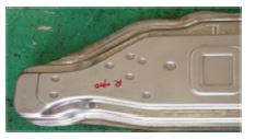
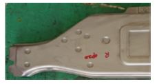
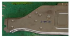
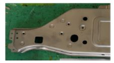
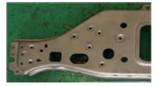
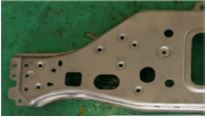
A mold with a double pressure source structure was manufactured that can increase the pressure of the contact surfaces of the upper and lower molds to ensure strong contact with the blank material in the forming & drawing process mold for radiator support parts. In other words, the double pressure source structure is designed to strongly contact the blank material with the punch, pad, blank holder, and die. Beads were applied to the flange parts at both ends to prevent wrinkles. Fig. 11 shows the Forming & Drawing process product using a square blank. Fig. 11(a) shows forming/drawing process product, Fig. 11(b) shows enlarged bursting part of forming/drawing process product. During the forming & drawing process, the blank material was formed into strong contact with punches, pads, blank holders, and dies, and bursting occurred at the corners at both ends. To improve this, the existing square blank was designed and molded by the blanking die to resemble the product shape as shown in Fig. 12, and a good molded product was obtained as shown in Fig. 13. Therefore, since the blank shape has a great influence on the occurrence of bursting of molded products, it is judged that consideration of this is necessary. In addition, although it is cost-effective to cut the coil material into square blanks and apply them to the press line, it was possible to produce good products by applying the square blanks to the press line through blanking processing. Fig. 14 shows a scene measuring shape accuracy with a 3D measuring device, and Table 4 shows the shape accuracy measurement results. From the shape accuracy measurement results, it can be seen that the springback phenomenon is within ±0.5 mm tolerance. Fig. 15 shows the measurement of shape precision by using the checking fixture for radiator support parts. The checking fixture was manufactured with a gap of 3.00 mm between the outer size of the radiator support parts and the outer size of the checking fixture shown in Fig. 15(a). Measurement of shape precision for radiator support parts is shown in Fig. 15(b), the change in the 3.00 mm gap between the outer size of the radiator support parts and the outer size of the checking fixture is measured.

Forming/drawing process product using rectangular blank

Final blank shape of forming/drawing process

Forming/drawing process product using final blank shape

Measurement scene of 3D coordinate measuring machine for radiator support parts
Measurement results of shape precision for radiator support parts

Measurement of shape precision for radiator support parts
6. Conclusion
This study developed automobile radiator support parts by applying press forming/drawing composite mold technology of 440 MPa high-strength steel plate. By applying the press forming/drawing composite mold technology of high-strength steel plate, material property evaluation, plate forming analysis, prototype mold design and production, and prototype performance evaluation were performed. The results of this study are summarized as follows.
- (1) In order to determine the mechanical properties of SGARC440, the material to be processed for radiator support parts, stress-strain diagrams were obtained through tensile testing, and the forming analysis results were obtained by applying the material properties during sheet metal forming analysis.
- (2) To produce radiator support products, a total of 6 processes were designed, including Forming & Drawing, Trimming, Flanging & Restriking, Piercing & Cutting, Piercing & Cam Piercing, and Piercing & Cutting, and a forming analysis was performed in the press forming/drawing composite mold process of 440 MPa high-strength steel plate. As a result, as the friction coefficient increased, the maximum forming load and thickness reduction increased.
- (3) It was found that the shape of the blank in the forming & drawing process mold for radiator support parts had a significant impact on the occurrence of bursting of the molded product.
- (4) By developing a forming/drawing mold structure that can strongly maintain the overall contact surface pressure on both the top and bottom of the blank material by applying high-tensile steel plate material, we have secured a composite mold technology that freezes elastic recovery stress, enabling continuous work at the press production site. Confirmed. Therefore, it was possible to improve the quality and productivity of radiator support parts by applying the forming/drawing composite mold technology of high-strength steel plate.
Acknowledgments
This study was supported by the National Research Foundation with the government, Ministry of Science and ICT (No. 2021R1A4A1031660), “Fanout semiconductor PR pattern high-speed automatic inspection equipment development (No. 20018441)”, a part of the Ministry of Trade, Industry and Energy's mechanical equipment industrial technology development project, and “Development of Ultra-Small Satellite with Hyperspectral and Visible Dual-Sensor Camera (No. RS-2022-00155901)”, a part of the space innovation project funded by the National Research Foundation of Korea.
REFERENCES
-
Park, D.-H., Kwon, H.-H., (2016), Development of automotive seat rail parts for improving shape fixability of ultra high strength steel of 980MPa, Journal of the Korean Society of Manufacturing Process Engineers, 15(5), 137-144.
[https://doi.org/10.14775/ksmpe.2016.15.5.137]

-
Park, D.-H., Tak, Y.-H., Kwon, H.-H., (2018), Process design of automobile seat rail lower parts using ultra-high strength, DP980 steel, Journal of the Korean Society of Manufacturing Process Engineers, 17(2), 160-167.
[https://doi.org/10.14775/ksmpe.2018.17.2.160]
-
Lee, C. M., Kim, J. H., Oh, W. J., Ryu, B. H., (2017), A study on the analysis for upper seat track of automobile using 1180 MPa ultra-high strength steel, Journal of the Korean Society for Precision Engineering, 34(8), 525-531.
[https://doi.org/10.7736/KSPE.2017.34.8.525]
-
Ko, D., An, J., Jang, M., Bae, J., Kim, C., Kim, B., (2008), Process design of seat rail in automobile by the advanced high strength steel of DP780, Transactions of Materials Processing, 17(3), 197-202.
[https://doi.org/10.5228/KSPP.2008.17.3.197]
-
Song, J., Kim, S., Park, S., Huh, H., (2006), Stress-based springback reduction of an AHSS front side member, Transactions of Materials Processing, 15(4), 295-303.
[https://doi.org/10.5228/KSPP.2006.15.4.295]
-
Kim, K., Kim, S., Yoo, K., Lee, C., Shim, H., (2014), Application of springback analysis in the development of a reinforce center pillar stamping die, Transactions of Materials Processing, 23(5), 297-302.
[https://doi.org/10.5228/KSTP.2014.23.5.297]
-
Kang, K., Kim, S., Ro, H., (2016), Change in springback tendency during forming of a hat-type product with high strength steel using a digital servo press, Transactions of Materials Processing, 25(1), 21-28.
[https://doi.org/10.5228/KSTP.25.1.21]
-
Song, J., Youn, K., Park, C., Heo, J., Kim, Y., (2017), Evaluation of servo press slide motion for springback reduction of high strength steel, Transactions of Materials Processing, 26(5), 277-285.
[https://doi.org/10.5228/KSTP.2017.26.5.277]
-
Lee, J., Kim, S., (2016), Automatic tool compensation for an UHSS automotive component using a compensation module, Transactions of Materials Processing, 25(2), 109-115.
[https://doi.org/10.5228/KSTP.25.2.109]
-
Jang, D., (2017), The process development of automotive light-weighting door using high strength steel, Transactions of Materials Processing, 26(1), 55-62.
[https://doi.org/10.5228/KSTP.2017.26.1.55]
-
Bang, G., Seong, H., Kwak, H., Kim, C., (2017), A study on stamping of the center pillar (high-strength steel-780MPa) Using Finite Element Analysis, Transactions of Materials Processing, 26(2), 87-94.
[https://doi.org/10.5228/KSTP.2017.26.2.87]
-
Kwak, J., Yoon, S., Kim, S., Park, J., Han, H., (2017), Prediction of deformation mechanism and fracture for an auto-part with advanced high strength steel using solid element and damage theory, Transactions of Materials Processing, 26(5), 293-299.
[https://doi.org/10.5228/KSTP.2017.26.5.293]
-
Cha, C., Lee, S., Ko, D., Kim, B., (2009), A study on the forming of automotive front side member part with ultra high strength steel of DP980, Transactions of Materials Processing, 18(1), 39-44.
[https://doi.org/10.5228/KSPP.2009.18.1.039]

Head researcher in Gyeongbuk Hybrid Technology Institute. His research interests are plastic working, sheet metal forming, hot and cold complex forging for automobile parts.
E-mail: pdh@ghi.re.kr

Director in the Department of R&D Center, Samsungtech Co., Ltd.. His research interest is sheet metal forming for automobile parts.
E-mail: ltg1119@naver.com

Professor in the Department of Mechanical Engineering, Daejin University. His research interests are metal forming for automobile parts and intellectual properties.
E-mail: hhkwon@daejin.ac.kr